background image

Outline s.r.l. - Via Leonardo da Vinci, 56 - 25020 Flero (Brescia) - Italy

Tel. +39-30-3581341 Fax +39-30-3580431 — Web Site: www.outline.it  E-Mail: [email protected]

14

Delivering the True Audio Experiences

I/O PORT

6

1

2

3

4

5

7

8

9

PORTA GENERICA DI INPUT-OUTPUT / 

GENERIC INPUT-OUTPUT PORT

La  porta  generica  di  input/output,  su  connettore  DB9, 
consente di interfacciare il processore con un sistema esterno 
di controllo (come un dispositivo di allarme anti-incendio o una 
pulsantiera per il cambio di livello). Le funzioni e le risposte ad 
un  input  sono  programmabili  via  remoto.  Queste  includono: 
mute  singoli  o  collettivi  degli  ingressi  e  delle  uscite, 
abbassamento o innalzamento del livello di ingressi e uscite, 
ecc...
Lo  schema  dei  pin  del  connettore  Db9  e  i  parametri  da 
rispettare sono raccolti nelle seguenti tabelle.

INPUT

Sono presenti due input in grado di rilevare un contatto pulito 
esterno tra i pin 1 - 2 (GPI 1a - GPI 1b) e tra i pin 3 - 4 (GPI 2a - 
GPI 2b).

OUTPUT

In seguito all’attivazione da parte del processore si genera la 
chiusura o l’apertura di un interruttore interno tra i pin 6 - 7 
(GPO 1a - GPO 1b) o tra i pin 8 - 9 (GPO 2a - GPO 2b).
Da impostazione di fabrica questi contatti sono normalmente 
aperti e vengono chiusi in seguito all’attivazione del comando 
da  remoto. Cambiando  le posizioni dei  jumper interni  X18 e 
X20,  si  modifica  il  comportamento  di  questi  output,  che 
possono essere settati individualmente per avere un contato 
normalmente chiuso che viene aperto in seguito al comando da 
remoto.  Lo  schema  della  posizione  dei  jumper  interni  è 
stampato sulla scheda elettronica all’interno del processore.

The generic input/output port, on a DB9 connector, gives you 
the  possibility  to  interface  the  processor  with  an  external 
control  system  (i.e.  a  fire  alarm  or  an  external  push-button 
controller  to  change  the  levels).  The  functions  and  the 
response of the device to an input are remotely programmable. 
The settings are including muting of all the channels or of each 
single  channel,  lowering  or  raising  the  level  of  inputs  and 
outputs, etc...
The pin configuration of the DB9 connector and the rated limits 
are reported in the following tables.

INPUT

The system is able to sense an external free contact between 
pin 1 - 2 (GPI 1a - GPI 1b) and between pin 3 - 4 (GPI 2a - GPI 2b).

OUTPUT

After  the  activation  command  given  by  the  processor,  the 
internal contacts will be opened or closed between pin 6 - 7 
(GPO 1a - GPO 1b) or between pin 8 - 9 (GPO 2a - GPO 2b).
By  factory  default  the  normal  status  of  these  contacts  is 
Normally Open and they are closed after the activation of the 
remote  command.  It  is  possible  to  change  this  response  by 
changing  the  configuration  of  the  internal  jumpers  X18  and 
X20.  Each  output  can  be  individually  set  in  order  to  have  a 
Normally  Closed  contact  that  will  be  open  after  the  remote 
command.  The  schematics  of  the  internal  jumpers 
configuration is reported on the printed circuit board inside the 
iP24.

Pin

Description

1

GPI 1a

2

GPI 1b / +5 V DC

3

GPI 2a

4

GPI 2b / +5 V DC

5

Ground

6

GPO 1a

7

GPO 1b

8

GPO 2a

9

GPO 2b

GPO (Output) Relay Ratings

Nominal Switching capacity (resistive load)

2 A 30 V DC - 0.5 A 125 V AC

Max switching power (resistive load)

60 W - 62.5 VA

Max switching voltage

220 V DC - 125 V AC

Max switching current

2 A

Type of selected contacts (internal)

NO or NC

GPI (Input) Opto-isolator  Ratings

Nominal control voltage

5 V DC

Max control voltage

12 V DC

Summary of Contents for IP24

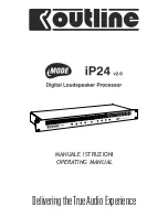
Page 1: ...DeliveringtheTrueAudioExperience MANUALE ISTRUZIONI OPERATING MANUAL ...

Page 2: ...ot expose the unit to rain and don t use it in locations with a high humidity level Ensure that no liquids or solid objects accidentally enter the unit should this occur stop using the unit and contact OUTLINE or specialist staff When connecting the unit ALWAYS check ground connection as required by technical and safety norms If the original cable is worn or damaged it must be replaced with anothe...

Page 3: ...cchio ha spinto Outline ad una scelta minimalista per quanto concerne l interfaccia hardware Outline iP24 è infatti completamente controllabile da remoto mediante utilizzo di un protocollo Ethernet standard tramite web browser che supporti la tecnologia Java da computer o tramite dispositiviApple iOS e OSX Thank you for choosing Outline iP24 for the management of your loudspeaker system We suggest...

Page 4: ...ng Rosso se l apparecchio è nello stato di mute impostabile da remoto o se il limiter è inserito indica che il circuito di limitazione sta intervenendo decisamente se il limiter non è inserito indica che il segnale è troppo elevato e sta clippando 1 STATUS this LED indicates that the device is working properly During the startup this LED remains red in order to indicate that the various checks are...

Page 5: ... digitali secondo il protocollo AES EBU 6 AES EBU IN 1 2 connettori di tipo XLR per il collegamento degli ingressi digitali secondo il protocollo AES EBU 7 I O PORT connettore di tipo DB9 per utilizzo tipo generico programmabile da remoto 8 RS 485 connettore RJ45 per la comunicazione seriale RS 485 con altre apparecchiature ad esempio amplificatori Outline serie T Funzione non ancora disponibile 1...

Page 6: ...visare il rivenditore Si consiglia di conservare l imballo da utilizzare in caso di trasporto dell unità in un secondo momento L unità Outline iP24 viene fornita con i seguenti accessori N 1 cavo di alimentazione Certificato di garanzia Questo manuale After unpacking the unit check very carefully for any damage If any damage is found please notify your dealer It is advisable to keep the packaging ...

Page 7: ...ate elettronicamente Il collegamento avviene tramite connettori XLR INGRESSIANALOGICI Gli ingressi hanno un impedenza nominale di k 100 Ω Per i segnali non bilanciati utilizzare i pin HOT segnale in fase e GND massa ed consigliabile collegare a massa il pin COLD è segnale invertito di fase per ridurre al minimo il rumore MOUNTING The iP 24 has been designed for 19 standard rack mounting and occupi...

Page 8: ...e provided and switch on the unit with the dedicated power button The unit will automatically turn on the STATUS LED will be red during the start up phase during this phase the unit will run also a LED check After this phase the STATUS LED will turn green or magenta depending on the input selected and the unit will be ready to be used CARATTERISTICHE FEATURES m Ingressi ed uscite analogiche e digi...

Page 9: ... is strongly suggested to switch on the router before any device COLLEGAMENTO CON ILCOMPUTER O iPAD iPHONE Il collegamento con il computer deve essere effettuato mediante la rete utilizzando cavi di rete CAT 5 ethernet Il collegamento ad un iPad iPhone o computer con wifi avviene tramite la costruzione di una rete wireless Sarà quindi indispensabile utilizzare un router wireless non fornito che si...

Page 10: ...attive altri network come in fiere grandi strutture o luoghi affollati usare reti wireless a 5 GHz non supportato da iPhone Per avere un controllo migliore sulle prestazioni della rete senza fili molti analizzatori wifi per computer tablet e telefoni sono disponibili sul web TROUBLESHOOTING If the DHCP is not available or if you do not know the IP address manually assigned to the iP24 unit you can...

Page 11: ... 22 kHz Crosstalk Inputs 108 dB 20 Hz 20 kHz MaxInputLevel Crosstalk Outputs 93 dB 20 Hz 20 kHz MaxInputLevel Crosstalk 93 dB 20 Hz 20 kHz MaxInputLevel SEZIONEANALOGICA Numero di ingressi analogici Due ingressi analogici bilanciati elettronicamente Impedenza di ingresso analogica bilanciato 100 Ω k Numero di uscite analogiche Quattro uscite analogiche bilanciate elettronicamente Impedenza di usci...

Page 12: ...or 1 x DB9 connectorwith two inputs and two free contact outputs Power supply connector 3 pin IEC connector SEZIONE DIGITALE Numero di ingressi digitali Due ingressi digitaliAES EBU un connettore due canali Number of digital outputs Quattro uscite digitaliAES EBU due connettori quattro canali Frequenze di campionamento supportate in ingresso 44 1 kHz 48 kHz 96 kHz 192 kHz THD N 140 dB 96 kHz 139 d...

Page 13: ...WER SUPPLY Power requirements 90 V 50 60 Hz 264 AC Power consumption 20 W PHISICAL Dimensions 1U standard EIA Height 44 mm 1 75 Width 483 mm 19 Depth mm 175 6 9 Weight Kg net 2 6 SEGNALAZIONI Ingresso analogico 20 dBu di sensibilità Verde 46 dBu 11 dBu Giallo 11 dBu 20 dBu Rosso 20 dBu clip Uscita analogica limiter escluso Verde 46 dBu 11 dBu Giallo 11 dBu 20 dBu Rosso 20dBu clip Uscita analogica ...

Page 14: ...nterno del processore The generic input output port on a DB9 connector gives you the possibility to interface the processor with an external control system i e a fire alarm or an external push button controller to change the levels The functions and the response of the device to an input are remotely programmable The settings are including muting of all the channels or of each single channel lower...

Page 15: ...Outline s r l Via Leonardo da Vinci 56 25020 Flero Brescia Italy Tel 39 30 3581341 Fax 39 30 3580431 Web Site www outline it E Mail info outline it 15 iMode Digital Loudspeaker Processor iP24 NOTE NOTES ...

Page 16: ...ine potrà lievemente differire dalla sua descrizione qui pubblicata ma comunque uguaglierà o supererà le caratteristiche qui specificate Outline 2015 Manuale d istruzioni codice Z OMIP24V2 0 Versione 150730 Stampato in Italia Outline carries out on going research for product improvement New materials manufacturing methods and design upgrades are introduced to existing products without prior notice...

Reviews: