Technical documentation
Technical documentation
STEM@ ed 06/01
24
EOLO MAIOR @
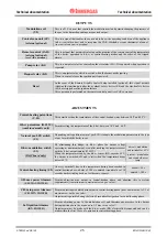
INPUTS
Gas valve supply
(VG)
This is a 230 V AC signal which, through an optoinsulator, indicates
input to the main coils of gas valve (Y1).
This permits the board to pinpoint and indicate the presence of a flame
and if necessary trigger the overheat. thermostat (E4) and stack
thermostat (E5).
During ignition, this restricts power to the modulation coil for 5
seconds
(see slow ignition adjustment trimmer).
230 Vac =
coils powered
0 Vac =
coils not powered
Flame lock
This is a signal from the igntion unit indicating burner ignition failure.
The alarm is displayed by the lighting up of LED H2
(red)
and with
code E01 on the CAR monitor
(if fitted).
To restore boiler operation after flame stop, the master switch (S5)
must be moved to RESET position or the RESET button of the CAR
(if fitted)
must be pressed.
230 Vac = flame
lock
0 Vac = stand-by /
burner ON
Control zone unit (CZ)
(external optional)
This sends signals to the board relating operation requests for any connected zone valves /
external pumps
(see control zone unit operation).
Remote control (CAR)
(
external optional)
(see CAR operation)
This sends SUM/WINT switch signals to the board relating to d.h.w. and central-heating
temperature adjustment and central heating request
(time,room temperature).
When the CAR is fitted, the room thermostat (TA) must be disconnected without restoring
the pre-existing bridge X20.
Main switch
(S5)
This is a double switch which, depending on its position either powers
or does not power the low-voltage circuit (24 Vdc) and indicates
whether d.h.w. + CAR function is enabled (
SUMMER
) or d.h.w. and
central-heating (
WINTER
)
.
Switch S5A
open= circuit OFF
closed = circuit ON
Switch S5B
open = SUMMER
closed = WINTER
System water pressure
switch
(S7)
When the primary circuit pressure is below 0.3 bar, this interrupts
power to relay K2 and prevents burner operation
Operation is indicated by alternate flashing of the LEDs H1 (
yellow
)
and H2 (
red
)
.
3 minutes after operation, the board also switches off the pump (M1),
interrupting power to relay K1.
Afterwards, if the contact does not close again, the circulator (M1) is
run for 15 seconds at intervals of 45 seconds for at most 60 times.
open =
no pressure
closed =
pressure OK
D.h.w. signal (S6)
(combined models only)
Indicates which request is under way
(d.h.w. or central heating).
Depends on position of d.h.w. microswitch (S6) of the 3-way valve.
closed =
d.h.w. request
open =
no d.h.w. request
Central-heating sensor
(B1)
This is a resistance variable in a way inversely proportionate to the
temperature of the primary circuit delivery water.
It is also used as a limit thermostat (90 ºC).
NTC sensor
10 kohm 25 ºC
D.h.w. sensor (B2)
(combined models only)
This is a resistance variable in a way inversely proportionate to the
temperature of d.h.w. outlet.
NTC sensor
10 kohm 25 ºC
Room thermostat (TA)
(external optional)
This is a clean contact switch that triggers central-heating when the
room temperature drops below that required.
open = central
heating OFF
closed = central
heating ON


