Technical documentation
Technical documentation
STEM@ ed 06/01
21
EOLO MAIOR @
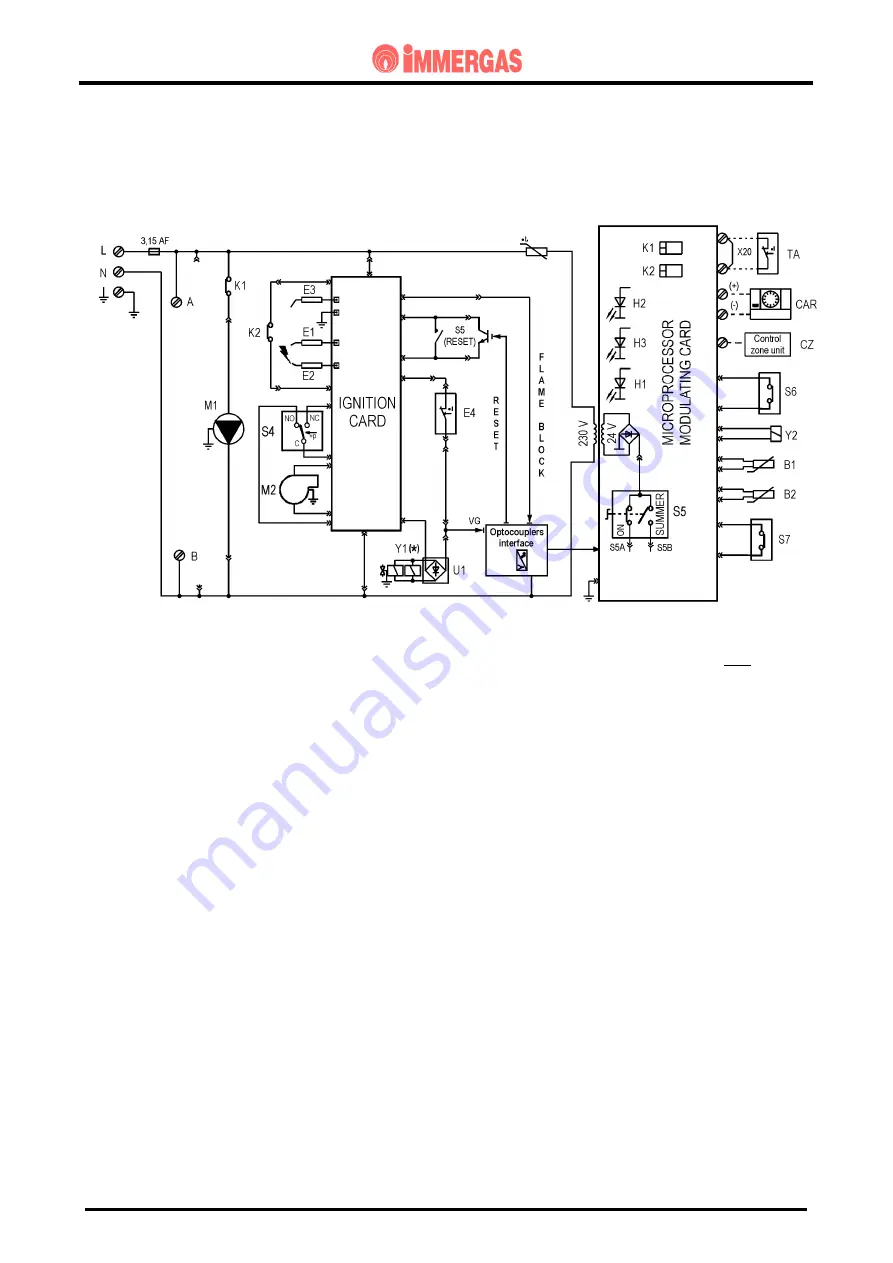
ELECTRICAL CIRCUIT
D.H.W. PHASE
(*) the main coils of the gas valve run at mains voltage rectified by means of a diode bridge (U1) only on the
Honeywell VK 4105 gas valve (diode bridge fitted on the valve connection connector)
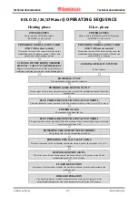
Operation
When the main switch (S5) is in "SUMMER" or "WINTER" position, it powers the modulation
board and enables operation in d.h.w. phase.
When the domestic hot water microswitch (S6) is closed, following a d.h.w. request, the low-voltage
circuit starts the pump (M1) through the contact of relay K1.
If the system water pressure switch (S7) reads a pressure in the primary circuit above minimum
value (
S7 switch closed
) and if the temperature read by the NTC heating sensor (B2) is below the
setting made on the control panel (
or on the CAR if fitted
) by means of the heating potentiometer,
the board closes the contact of the requested relay (K2).
This way, the ignition unit (IGNITION CARD) starts the ignition cycle by first checking the correct
position of the flue pressure switch (S4) and then powering the fan (M2).
After the contact of flue pressure switch (S4) has been deviated by fan operation (M2), the unit
(IGN. BOARD) powers the ignition electrodes (E1-E2) and, with the consensus of the overheat.
safety thermostat (E4), the main coils of gas valve (Y1).
Burner ignition is detected by the ignition unit (IGNITION CARD) by means of the ionisation
electrode (E3).


