


2
Hinweise für den sicheren Gebrauch
Dieses Gerät entspricht der Richtlinie für elektroma-
gnetische Verträglichkeit 89/336/EWG und der Nie-
derspannungsrichtlinie 73/23/EWG.
Beachten Sie unbedingt die folgenden Punkte:
●
Das Gerät ist nur zur Verwendung in Innenräumen
geeignet. Schützen Sie es vor Tropf- und Spritz-
wasser, hoher Luftfeuchtigkeit und Hitze (zulässi-
ger Einsatztemperaturbereich 0 – 40 °C).
●
Stellen Sie keine mit Flüssigkeit gefüllten Gefäße,
z. B. Trinkgläser, auf das Gerät.
●
Nehmen Sie das Gerät nicht in Betrieb bzw. ziehen
Sie sofort den Netzstecker aus der Steckdose:
1. wenn sichtbare Schäden am Gerät oder an der
Netzanschlussleitung vorhanden sind,
2. wenn nach einem Sturz oder Ähnlichem der
Verdacht auf einen Defekt besteht,
3. wenn Funktionsstörungen auftreten.
Lassen Sie das Gerät in jedem Fall in einer Fach-
werkstatt reparieren.
●
Eine beschädigte Netzanschlussleitung darf nur
durch den Hersteller oder durch eine autorisierte
Fachwerkstatt ersetzt werden.
●
Ziehen Sie den Netzstecker nie am Kabel aus der
Steckdose, fassen Sie immer am Stecker an.
●
Verwenden Sie für die Reinigung nur ein trockenes,
weiches Tuch, niemals Wasser oder Chemikalien.
●
Wird das Gerät zweckentfremdet, nicht richtig an-
geschlossen, falsch bedient oder nicht fachgerecht
repariert, kann keine Haftung für daraus re-
sultierende Sach- oder Personenschäden und
keine Garantie für das Gerät übernommen werden.
3
Einsatzmöglichkeiten
Das Mischpult MPX-204E/SW mit vier Stereo-Ein-
gangskanälen, zwei Mono-Mikrofonkanälen und in-
tegrierter Echofunktion ist für beliebige DJ-Anwen-
dungen im privaten oder professionellen Bereich
geeignet.
Das Gerät kann sowohl frei aufgestellt als auch in
ein Bedienpult eingebaut werden. Es eignet sich
ebenso für die Montage in ein Rack (482 mm/19").
Für die Rackmontage wird eine Höhe von 5 HE (Hö-
heneinheiten) = 222 mm benötigt.
4
Gerät anschließen
Vor dem Anschließen von Geräten bzw. vor dem
Ändern bestehender Anschlüsse das Mischpult aus-
schalten.
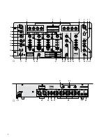
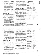
1) Die Stereo-Tonquellen an die entsprechenden
Cinch-Eingangsbuchsen der Kanäle 1 – 4 an-
schließen (weiße Buchse L = linker Kanal; rote
Buchse R = rechter Kanal):
– Geräte mit Line-Pegel-Ausgang (z. B. MiniDisk-
Recorder, CD-Spieler, Kassettenrecorder) an
die Buchsen CD oder LINE (38);
– Plattenspieler mit Magnetsystem an die Buch-
sen PHONO (31).
Den Masseanschluss des Plattenspielers mit
der jeweiligen darüber liegenden Klemm-
schraube GND (32) verbinden.
2) Ein DJ-Mikrofon an die XLR-Buchse (8) auf der
Frontplatte oder an die 6,3-mm-Klinkenbuchse
MIC 1 (40) auf der Rückseite anschließen.
3) Ein zweites Mikrofon kann an die 6,3-mm-Klinken-
buchse MIC 2 (39) angeschlossen werden.
4) Den bzw. die Verstärker an den symmetrischen
XLR-Masterausgang (34) und/oder an den asym-
metrischen Cinch-Masterausgang (35) anschlie-
ßen.
5) Ist eine Monitoranlage vorhanden, den Verstär-
ker der Monitoranlage an den Ausgang BOOTH
(36) anschließen.
6) Sollen Tonaufnahmen gemacht werden, das Auf-
nahmegerät an den Ausgang REC (37) anschlie-
ßen. Der Aufnahmepegel ist unabhängig von der
Stellung des Masterfaders (27).
7) Über einen Stereo-Kopfhörer kann sowohl der Pre
Fader-Pegel jedes Stereo-Eingangskanals sowie
das laufende Musikprogramm vor dem Master-
fader (27) abgehört werden (siehe Kap. 5.6 „Vor-
hören über einen Kopfhörer“). Den Stereo-Kopf-
hörer (Impedanz
≥
8
Ω
) an die Buchse PHONES
(28) anschließen.
8) Für eine optimale Pultbeleuchtung kann an die
XLR-Buchse LAMP (5) eine Schwanenhalsleuchte
(12 V/5 W max.) angeschlossen werden, z. B. die
Leuchte GNL-405 aus dem Programm von „img
Stage Line“. Die Leuchte wird mit dem Mischpult
ein- und ausgeschaltet.
9) Zuletzt den Stecker des Netzkabels (33) in eine
Steckdose (230 V~/50 Hz) stecken.
5
Bedienung
Vor dem Einschalten sollten der Masterfader (27)
und der Monitorregler (7) auf Minimum gestellt wer-
den, um Einschaltgeräusche zu vermeiden. Dann
das Mischpult mit dem Ein-/Ausschalter POWER (6)
einschalten. Zur Anzeige der Betriebsbereitschaft
leuchtet die LED über dem Schalter. Anschließend
die angeschlossenen Geräte einschalten.
Vorsicht! Stellen Sie die Lautstärke der Audioan-
lage und die Kopfhörerlautstärke nie sehr hoch ein.
Hohe Lautstärken können auf Dauer das Gehör
schädigen! Das menschliche Ohr gewöhnt sich an
große Lautstärken und empfindet sie nach einiger
Zeit als nicht mehr so hoch. Darum eine hohe Laut-
stärke nach der Gewöhnung nicht weiter erhöhen.
Soll das Gerät endgültig aus dem
Betrieb genommen werden, übergeben
Sie es zur umweltgerechten Entsorgung
einem örtlichen Recyclingbetrieb.
Achtung! Das Gerät wird mit lebensgefährlicher
Netzspannung (230 V~) versorgt. Neh-
men Sie deshalb niemals selbst Ein-
griffe am Gerät vor. Durch unsachge-
mäßes Vorgehen besteht die Gefahr
eines elektrischen Schlages. Außerdem
erlischt beim Öffnen des Gerätes jeg-
licher Garantieanspruch.
2
Safety Notes
This unit corresponds to the directive for electro-
magnetic compatibility 89/336/EEC and to the low
voltage directive 73/23/EEC.
Please observe the following items in any case:
●
The unit is suitable for indoor use only. Protect it
against dripping water and splash water, high air
humidity, and heat (admissible ambient tempera-
ture range 0 – 40 °C).
●
Do not place any vessel filled with liquid on the
unit, e. g. a drinking glass.
●
Do not operate the unit or immediately disconnect
the plug from the mains socket
1. if there is visible damage to the unit or to the
mains cable,
2. if a defect might have occurred after the unit
was dropped or suffered a similar accident,
3. if malfunctions occur.
In any case the unit must be repaired by skilled
personnel.
●
A damaged mains cable must be replaced by the
manufacturer or authorized, skilled personnel only.
●
Never pull the mains cable for disconnecting the
mains plug from the socket, always seize the plug.
●
For cleaning only use a dry, soft cloth; never use
chemicals or water.
●
No guarantee claims for the unit and no liability for
any resulting personal damage or material damage
will be accepted if the unit is used for other purposes
than originally intended, if it is not correctly con-
nected, operated or not repaired in an expert way.
●
Important for U. K. Customers!
The wires in this mains lead are coloured in
accordance with the following code:
blue = neutral; brown = live
As the colours of the wires in the mains lead of this
appliance may not correspond with the coloured
markings identifying the terminals in your plug,
proceed as follows:
1. The wire which is coloured blue must be con-
nected to the terminal in the plug which is
marked with the letter N or coloured black.
2. The wire which is coloured brown must be con-
nected to the terminal which is marked with the
letter L or coloured red.
3
Applications
The mixer MPX-204E/SW with four stereo input
channels, two mono microphone channels and inte-
grated echo function is suitable for any private or
professional DJ applications.
The unit can either be placed as desired or be in-
stalled into a console. It can also be mounted into a
rack (482 mm/19"). For rack installation, a height of
5 RS (rack spaces) = 222 mm is required.
4
Connection
Prior to connecting units or to changing existing
connections, switch off the mixer.
1) Connect the stereo audio sources to the corre-
sponding phono input jacks of channels 1 to 4
(white jack L = left channel; red jack R = right
channel):
– Units with line level output (e. g. minidisk re-
corder, CD player, cassette recorder) to the
jacks CD or LINE (38);
– Turntables with magnetic system to the jacks
PHONO (31). Connect the ground of the turn-
table to the corresponding terminal screw
GND (32) above the jacks.
2) Connect a DJ microphone to the XLR jack (8) on
the front panel or to the 6.3 mm jack MIC 1 (40)
on the rear panel.
3) A second microphone can be connected to the
6.3 mm jack MIC 2 (39).
4) Connect the amplifier or amplifiers to the bal-
anced XLR master output (34) and/or to the un-
balanced phono master output (35).
5) If a monitoring system exists, connect the am-
plifier of the monitoring system to the output
BOOTH (36).
6) For sound recordings, connect the recorder to
the output REC (37). The recording level is inde-
pendent of the position of the master fader (27).
7) Via stereo headphones, both the prefader level of
each stereo input channel and the current music
programme can be monitored ahead of the master
fader (27) [see chapter 5.6 “Prefader listening via
headphones”]. Connect the stereo headphones
(impedance
≥
8
Ω
) to the jack PHONES (28).
8) For an optimum console illumination, a goose-
neck light (12 V/5 W max.) can be connected to
the XLR jack LAMP (5), e. g. GNL-405 from the
“img Stage Line” range. The light can be switched
on and off via the mixer.
9) Finally connect the plug of the mains cable (33)
to a socket (230 V~/50 Hz).
5
Operation
Prior to switching on, the master fader (27) and the
monitor control (7) should be set to minimum to pre-
vent switching noise. Switch on the mixer with the
switch POWER (6). The LED above the switch lights
up to indicate that the unit is ready for operation.
Then switch on the connected units.
Caution! Never adjust the audio system or the
headphones to a very high volume. Permanent
high volumes may damage your hearing! The
human ear will get accustomed to high volumes
which do not seem to be that high after some time.
Therefore, do not further increase a high volume
after getting used to it.
If the unit is to be put out of operation
definitively, take it to a local recycling
plant for a disposal which is not harmful
to the environment.
Attention! The unit is supplied with hazardous
mains voltage (230 V~). Leave servicing
to skilled personnel only. Inexpert hand-
ling may cause an electric shock hazard.
Furthermore, any guarantee claim will
expire if the unit has been opened.
5
GB
D
A
CH


