background image


ResMark 5000 High-Resolution

Section 2: Quick Start

400386 Operations Manual Rev A

Page  16 

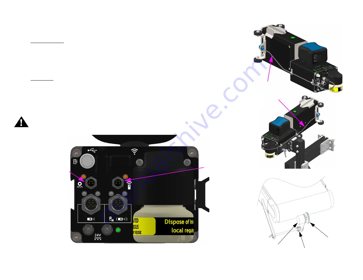
Step 9: Mount Photosensor and Encoder

Photosensor

1. Mount the photosensor (kit 400203) in the roller bracket attached to the Printer Module and 

route the cable as shown in one of the two shown configurations depending on the application.

2. Insert the photosensor cable connector into the appropriate connector on the rear of the 

Primary print head Ink Supply Module.

Encoder

1. Install the encoder (kit 400504) in a location where it will accurately measure the speed of the 

conveyor.

2. Install it in contact with the conveyor belt or with a roller moving the same speed as the 

conveyor.

3. Insert the encoder cable into the Primary print head Ink Supply Module.

CAUTION: 

  Do not excessively pre-load the encoder wheel. A radial force of over 18,14 kg [40 

lbs] will reduce the life of the bearings.

Encoder

Input

Photosensor 

Input

Conveyor

Encoder

Spring

Encoder Wheel

Photosensor 

Mounting & 

Cable 

Routing

Summary of Contents for ResMark 5000

Page 1: ...Operations Manual 1 Missouri Research Park Drive St Charles MO 63304 Service Line 1 800 526 2531 Illinois Tool Works Inc 2021 ResMark 5000 High Resolution System 400386 Revision A ...

Page 2: ...0386 The information contained in this manual is correct and accurate at the time of its publication ITW reserves the right to change or alter any information or technical specifications at any time and without notice 2022 Illinois Tool Works Inc All rights reserved ...

Page 3: ...ies a limited warranty The inks and conditioners used with the ResMark 5000 High Resolution System carry a limited warranty For all warranty terms and conditions contact Diagraph an ITW Company for a complete copy of the Limited Warranty Statement or visit Diagraph com Warranty ResMark 5000 System ...

Page 4: ...osensor and Encoder 16 Step 10 Daisy Chain Print Heads HMI and or Customer Network 17 Step 11 Cap Unused Ports 19 Step 12 Create a Message and Control the Print System 19 Section 3 Maintenance and Shutdowns 20 System Maintenance 20 Printer Module Maintenance 20 Ink Supply Module Maintenance 21 Printer System Shutdown 21 Cleaning Maintenance System 22 Printer Module Replacement 23 Section 4 Trouble...

Page 5: ...ms 40 ResMark 5000 Main CPU PCB Assembly 40 ResMark 5000 Internal Wiring Diagram 41 Appendix D Ink 42 Storage Life of a FACTORY SEALED Bottle of Ink 42 Use Life of an OPENED Cartridge of Ink 42 Appendix E Updating the ISM via USB or Ethernet 42 Appendix F Software Interface 42 Appendix G Part Numbers 43 System 43 Print Head Replacement Parts 44 Bracketry 45 Fittings 46 Cables 46 Service Parts and ...

Page 6: ...tains hazardous voltage 90VDC Disconnect from mains power before Performing preventive maintenance Performing any repairs to the unit Servicing the equipment in any manner ESD protection should be worn when servicing internal printed circuit boards After service to the equipment is completed replace all protective devices such as grounding cables and covers before operating the equipment It is ext...

Page 7: ...The figure at right illustrates a typical installation System Components 1 Bracketry Kit Item 1 2 Print Head Item 2 3 HMI Item 3 4 Power Supply Item 4 5 Photosensor Item 5 6 Encoder Item 6 7 Power Cord not shown 8 Ethernet Cable not shown 9 Software not shown 10 Ink not included TYPICAL INSTALLATION 4 3 1 2 5 6 ...

Page 8: ...6 Operations Manual Rev A Page 8 Step 1 Assemble Bracketry to Conveyor 1 Firmly tighten all fasteners NOTE Ensure bracketry is square and level PRINT HEAD CONVEYOR MOUNT 400201 FOR Mark 2 PRINT HEAD 400204 FOR Mark 4 PRINT HEAD OPTIONAL HMI CONTROLLER MOUNT ...

Page 9: ...Bracketry ROLLER RETRACTING BRACKET MOUNT for Mark 2 Print Head 400201 DOVETAIL ADAPTER AND RETRACTING BRACKET AND CAN BE MOUNTED ON EITHER SIDE OF PRINT HEAD ROLLER RETRACTING BRACKET MOUNT for Mark 4 Print Head 400204 NOTE The dovetail adapter and mounting bracketry can be mounted on either side of the print head system ...

Page 10: ...Connect Power Supply 1 Install power supply with power cord mains facing the conveyor and DC output facing out towards the rear of the print system 2 Firmly tighten fasteners to bracketry or convenient location NOTE One power supply pack can power up to two print heads in any combination of Mark 2 or Mark 4 ...

Page 11: ... have the photocell mounted to it on the leading edge 3 Ensure the power connector is fully inserted and the threaded barrel is finger tight 4 Connect any downstream print heads from the Primary These are considered Secondary 5 Only one Secondary print head can be powered by an upstream print head An additional power supply will be required for every two print heads on a daisy chain regardless of ...

Page 12: ...t vertical bracket with print head horizontally to within 6 mm 1 4 in of the carton 4 Use the dovetail tool less handle to make fine adjustments between the print head rollers and carton to within 1 mm 2 mm 04in 08 in NOTE Print head print gap can be adjusted to be larger in heavy debris environment but must be balanced with print quality CLEAN PRIME BUTTON AT TEMPERATURE LED RECIRCULATION LED HEA...

Page 13: ... head on the ink supply The green LED should be illuminated and if not adjust the bracketry up or down as needed 4 The print head is calibrated to within 1 5 Print Head Tilt 1 Loosen the tool less handle on the side of the Printer Module 2 Rotate the Printer Module to an angle that creates perpendicular print on the product 3 Tighten the tool less handle Maximum Print Head Tilt from Vertical When ...

Page 14: ...ation label facing towards the rear of the print head Note The cartridge is equipped with smart chip technology that will detect the presence of the cartridge The cartridge can only be installed in one orientation as it is keyed to the Ink Supply receiver which will guarantee connection to the smart chip When the cartridge is installed the state of the ink gauge LED indicators on the top of the In...

Page 15: ...The Clean Prime button LED will illuminate during this time and print will be disabled After an additional 5 seconds the LED will turn off and print will be re enabled 7 Print can be tested by slowly passing a sheet of paper in front of the print head after pressing the All Channel Print button A solid image will print for approximately 3 seconds 8 If the Mark 2 sample is 50 8 mm 2 in tall with no...

Page 16: ...onnector on the rear of the Primary print head Ink Supply Module Encoder 1 Install the encoder kit 400504 in a location where it will accurately measure the speed of the conveyor 2 Install it in contact with the conveyor belt or with a roller moving the same speed as the conveyor 3 Insert the encoder cable into the Primary print head Ink Supply Module CAUTION Do not excessively pre load the encode...

Page 17: ...ow Up to eight print heads can be daisy chained together 3 Install the HMI Controller on appropriate bracketry 4 Connect the HMI or Laptop PC via Ethernet cable 400374 2 0 as shown in the below diagrams NOTE Alternatively the Primary print head can be connected to the HMI via wireless Consult the create and control manual 400463 Standalone System with HMI One Print Head Standalone System with HMI ...

Page 18: ...d System with Optional HMI One Print Head Networked System with Optional HMI Two or More Print Heads HMI PRIMARY PRINT HEAD FROM UPSTREAM PRINT HEAD OR CUSTOMER NETWORK TO DOWNSTREAM PRINT HEAD OR HMI CUSTOMER NETWORK HMI SECONDARY PRINT HEAD PRIMARY PRINT HEAD SECONDARY PRINT HEAD CUSTOMER NETWORK ...

Page 19: ...HMI 24VDC POWER ENCODER USB DEVICE OR FIRMWARE UPGRADE HAS BUILT IN CAP ETHERNET FROM UPSTREAM PRINT HEAD OR CUSTOMER NETWORK The Primary print head should have all ports populated with a cable Exceptions Only one head in the daisy chain cap Ethernet and one power port No encoder cap encoder port Wireless communication cap Ethernet ports No HMI cap Ethernet port Secondary print heads will have mos...

Page 20: ... on the print head orifice plate that disrupt the ink droplet path For best preventative maintenance practices do the following 1 Remove excessive debris build up corrugate dust glue strands and the like on and around the front of the print head by using maintenance spray 5760695 on a clean lint free cloth 6600171 and wiping the front plate and enclosure If debris build up is noted on the enclosur...

Page 21: ...e receiver needle area to remove any debris or ink residue NOTE Do not use Maintenance Spray directly in this area Printer System Shutdown Shutdowns of 1 Week or More 1 Repeat the steps in Printer Module Maintenance on page 20 2 Install shipping cap onto the front of the PM and the shipping plugs into the cartridge receiver and vent on the ISM 3 Disconnect power from the mains power cord Startup F...

Page 22: ...ill not activate Make sure all ink faults are corrected before attempting a cleaning cycle 1 The cleaning feature can be accomplished by two methods Manually From the rear of the print head Press the Clean Prime button The cleaning cycle will initiate Automatically By default the print head is programmed to run a cleaning cycle every 4 hours To change the timing consult Create Control manual 40046...

Page 23: ...inting Diagraph leverages the remanufacturability of its high resolution technology by making it easy to remove the Printer Module on the fly and live no need to disconnect ink or electrical lines The Printer Module can be returned to the factory and disassembled cleaned down to the engine level and returned to normal service making it more economical and green for the environment Printer Module s...

Page 24: ...fractures in print channels Possible Cause Debris on front plate air in channel Action Run Cleaning System using a foam swab to assist in removal of debris Problem Missing Channels and Channel fractures in print channels Possible Cause Excessive debris on front plate air in channel Action Wipe front plate and run Cleaning System using a foam swab to assist in removal of debris Install shipping cap...

Page 25: ...on Check front to back level of print head Problem Fuzzy Print Possible Cause Print head too far away from substrate Action Move print head to within 1 8 from product Problem Occasional checkerboard print pattern Possible Cause Encoder slipping or bouncing on belt Action Tighten encoder on belt replace encoder o rings if required replace conveyor belt with smooth seamless type belt ...

Page 26: ...nternal encoder Action Check for correct encoder must use part 400206 Problem Short image dark print checkerboard pattern Possible Cause Incorrect encoder or wheel size or incorrect line speed set too high if using internal encoder Action Check for correct encoder must use part 400206 Problem Backwards print Possible Cause Incorrect print direction specified in set up Action Re do print head set u...

Page 27: ...y OFF Replace PCB PCB Board interior Insulate PCB assembly from surrounding metal objects Connect power Interior LED 14 heartbeat ON Unlock J12 re seat ribbon cable and engage lock OFF Replace PCB Ink pump not working during Clean Prime cycle PC Board LED11 Green indicates a print head is signaling for the Liquid Pump to turn on ON Replace ISM OFF Replace PCB Air in System Clean both orifice plate...

Page 28: ...s installed and not damaged Ensure waste bottle is installed and tight If waste bottle is normal replace PCB or ISM Print Head never reaches temp At Temperature LED on membrane never turns ON Ambient Too Cold Measure ambient temperature with appropriately calibrated device Less than 4 C 40 F Consult factory technical support Printer Module Membrane At Temperature and Heater LEDs At Temp Red and He...

Page 29: ...hat objects on the far side of conveyor do not trip the photosensor 4 Check that color differences in product do not cause multiple photosensor trips at the farthest sensing distance NOTE The test object should be a sample of the actual product NOTE If the green power LED or yellow LED on the photosensor fails to illuminate when an object is placed in front of the photosensor it indicates that the...

Page 30: ...igh Resolution Appendix A System Specifications 400386 Operations Manual Rev A Page 30 Appendix A System Specifications System 830mm 32 7in 615mm 24 2in 433mm 17 0in 141mm 5 6in 290mm 11 4in 156mm 6 1in 546mm 21 5in ...

Page 31: ...mm 7 72in Width 330 7mm 13 02in Depth 41 3mm 1 62in IP Rating IP34 estimated Enclosure HDPE Plastic User Interface Graphical User Interface with on screen keyboard Fonts True Type Display 274 3mm 10 5in LCD with TFT touch screen 1920 X 1280 pixels Storage Memory 64GB SSD 4GB RAM Ports 2 USB A 3 0 port 1 Gigabit Ethernet port Electrical Input 12VDC 3A Environment Ambient operating temperature 0 C 4...

Page 32: ...per minute 200 dpi Higher line speeds achievable with reduction of dpi Print Resolution 384 128 Engine 128 addressable channels 51mm 2in solid print height Throw Distance Print Gap Up to 6 4mm 1 4in for alphanumeric 3 2mm 1 8in recommended for best barcode quality Ink Type ScanMark Pigmented Ink for porous substrates black Environment Ambient operating temperature 4 C to 40 C 40 F to 104 F Operati...

Page 33: ...t per minute 200 dpi Higher line speeds achievable with reduction of dpi Print Resolution 768 256 Engine 256 addressable channels 102mm 4n solid print height Throw Distance Print Gap Up to 6 4mm 1 4in for alphanumeric 3 2mm 1 8in recommended for best barcode quality Ink Type ScanMark Pigmented Ink for porous substrates black Environment Ambient operating temperature 4 C to 40 C 40 F to 104 F Opera...

Page 34: ...ad 2 Mark 2 Print Head 3 HMI 4 Conveyor 5 Product and Print Direction 6 Print Head Bracketry 7 Ink Status Communications LED 8 Encoder 9 Photosensor 10 Encoder Cable 11 Photosensor Cable 12 Ethernet Cable HMI to Print Head 13 Ethernet Cable Print Head to Print Head 14 Throw Distance 1mm 2mm 04in 08in Recommended 3 1 2 4 5 9 11 8 6 6 7 10 14 12 13 ...

Page 35: ...stem Specifications 400386 Operations Manual Rev A Page 35 Customer System Connection PHOTOSENSOR ETHERNET TO DOWNSTREAM PRINT HEAD OR HMI 24VDC POWER ENCODER USB DEVICE OR FIRMWARE UPGRADE ETHERNET FROM UPSTREAM PRINT HEAD OR CUSTOMER NETWORK ...

Page 36: ...ture buttons are activated the ink and vacuum pumps turn ON and the print is disabled During Recirculation the ship cap should be installed When using the recirculation feature downstream pressure builds allowing optimal conditions for removing unwanted air from the ink supply system and wetting of the print engine ink pathways Finally the ISM provides a means of ink waste collection from the use ...

Page 37: ...tle located at the rear of the ISM A Clean cycle can be manually initiated by pushing the Clean Prime button located on the rear of the ISM or it can also be programmed to run at specified times by using the control software All Channel Print The functionality to check for 100 print from the print head is available locally at the print head This function can be performed by momentarily pressing th...

Page 38: ...in place to allow for additional printing Ten more milliliters of ink are allowed The time to consume this volume is variable based on application parameters Once this 10ml volume is consumed the system will change to an Ink Error state The LED s on the ink gauge will fast flash as will the red primary LED In addition print will be disabled It will take approximately 30 seconds to refill the reser...

Page 39: ...ync Print Trigger Photosensor The photosensor detects when a product is about to pass by the PM nozzle plate and signals the CPU to start a print cycle The photosensor signal is active low and it must remain low for at least one encoder pulse Once a print cycle starts it continues to completion regardless of what the photosensor signal does The system is compatible with through beam retro reflecti...

Page 40: ...net Flashes indicates network traffic JC2 Smart Chip 4 pin J22 Optional Serial USB A LED4 Ethernet Flashes indicates network traffic J3 Power 24VDC 3 8 32 threaded LED5 Photosensor Indicates product detect J4 Encoder M8 LED6 Power Indicates power to ISM J5 Photosensor M8 LED7 Float Switch Indicates ink full in reservoir J6 Ethernet Input M12 LED8 Vacuum Pump Indicates ON J7 Ethernet Output M12 LED...

Page 41: ...Operations Manual Rev A Page 41 ResMark 5000 Internal Wiring Diagram 24VDC SMART CHIP PRINT ENGINE VACUUM PUMP INK PUMP PRINTER MODULE PRIMARY LED INK RESERVOIR FLOAT SWITCH MEMBRANE SWITCH LED ARRAY INK WASTE FLOAT SWITCH COUPLING J10 J10 J12 JC2 J15 J9 J14 ...

Page 42: ...f the ink NOTE Do not shake the ink cartridge before use Agitating the ink may introduce air into the Print Head If shaken the bottle must sit for at least two hours before use Use Life of an OPENED Cartridge of Ink ScanMark 3 months from opening NOTE Exposure to air temperature and relative humidity will affect the useful life of the ink Appendix E Updating the ISM via USB or Ethernet For instruc...

Page 43: ...ers 400386 Operations Manual Rev A Page 43 Appendix G Part Numbers System Item Part No Description 1 404050DG HMI Controller 2 400001PDG Mark 2 Print Head ScanMark Domestic or European 3 400004PDG Mark 4 Print Head ScanMark Domestic or European 1 2 3 ...

Page 44: ... 2 400003PDG Printer Module Mark 2 ScanMark Domestic or European 3 400005PDG Printer Module Mark 4 ScanMark Domestic or European 4 400205 PCB Rear Plate Vacuum Module Assembly 5 400214 Roller with Mounting Bracketry Mark 2 6 400215 Roller with Mounting Bracketry Mark 4 7 5760835 Roller Replacement Kit 5 Rollers 8 400209 Orifice Ship Cap Mark 2 9 400210 Orifice Ship Cap Mark 4 1 2 3 4 5 6 9 7 7 8 ...

Page 45: ...stic or European 3 400202 Retractor Mounting Bracket Kit 4 400204 Mounting Bracket Kit with Retractor and Rollers for Mark 4 Print Head Domestic or European 5 5765249 T Base Stand Kit 6 5765250 HMI Controller Conveyor Mounting Bracket Kit 7 5760354 Multi Print Head Conveyor Mounting Kit 8 5760355 Print Head Floor Mounting Kit 9 5760356 Multi Print Head Floor Mounting Kit w 24 Bar 5760357 Multi Pri...

Page 46: ...00371 2 0 Cable Ethernet Print Head to Print Head 2m 4 400371 3 0 Cable Ethernet Print Head to Print Head 3m 5 400374 2 0 Cable Ethernet Print Head to RJ45 2m 6 400227 RJ45 Ethernet Coupler 7 400530 Extension Cable M8 5m Photosensor or Encoder NOTE Other lengths available consult the factory Part No Description Contents 400212DG Ink ScanMark Pigmented Porous Media Black 2 PACK 2 Cartridge 500mL 40...

Page 47: ...coder Assembly w Mounting Bracket 25ft Cable 3 400211 Beacon Remote 4 400216 Plug M8 Connector pack of 10 5 400217 Plug M12 Connector pack of 10 6 400218 Cap 5 16 Power Connector pack of 10 7 400219 Shipping Plug Ink Supply Module 8 400220 Shipping Plug Printer Module 9 400221 Wheel Replacement Encoder 10 400222 Power Supply and Mounting Bracket Hardware 11 400225 Waste Bottle pack of 6 1 2 7 8 9 ...

Reviews: