background image

GB-4

nuts, bolts and other fasteners are properly secured 

and that the guards/covers are in place. 

10. Before starting the machine, look into the feeding 

chute and make certain that it is empty. 

Operation


1. 

Shred only in daylight or good artificial light. 

2.  Never use the garden shredder in the rain or wet con-

ditions. Do not operate the garden shredder is poorly 

ventilated areas, or in areas where flammable materi

-

als are present. 

3.  Do not tilt the garden shredder when the motor is 

switched on. 

4.  During use, keep your face and body away from the 

feeding chute. 

5.  Keep proper balance at all times. Do not overreach. 

Never stand at a higher level that the base of the ma-

chine when feeding material into it. 

6.  Do not allow processed material to build up in the 

discharge zone, this may prevent proper discharge 

and result in a kickback of material through the feed 

intake. 

7.  Switch off and wait until the blades have stopped ro-

tating, if the garden shredder is to be moved to a dif-

ferent work area. 

8.  Do not put your hands in the feeding chute or near the 

rotating blades. 

9.  Never pick-up or carry the garden shredder while the 

motor is running. 

10. The shredder must be used in the upright position 

only. Do not operate the shredder if it is lying on its 

side. 

11. Do not feed foreign objects such as stones, glass, 

metal, earth or plastics into the garden shredder. 

12. Switch off and disconnect from the mains supply: 

– Whenever you leave the garden shredder unat-

tended. 

– Before clearing a blockage. 
– Before checking, cleaning or working on the garden 

shredder. 

13. If the garden shredder starts to vibrate abnormally 

check machine immediately. 

14. Keep all handles and grips dry and clean. Make sure 

that all exterior nuts, bolts and screws are tight and 

secure before operating the garden shredder. 

15. If you need to use an extension cable when using the 

garden shredder, it should be rated at 8A minimum. 

16. Use only extension cords suitable for outdoor use, 

preferable with a high visibility cable colour. 

17. For extension cables up to 25 metres, use a wire 

cross section of 1.5 mm

2

. For extension cables over 

25 metres but less than 40 metres, use a wire cross 

section of 2.5 mm

2

18. Always replace a damaged extension cable. Do not 

use if damaged. 

19. If the insulation on a power cable or extension lead 

is found to be cut or damaged, do not touch it! Dis-

connect the power supply immediately and have the 

damaged cable replaced. Do not repair damaged 

cables. 

20. Always switch off at the mains, before disconnecting 

any plug, cable connectors or extension cables. 

21. Always wind the cable carefully, avoiding kinking. 

22. Always follow the manufacturer’s instructions. 

23. Attention! Through poor conditions of the electri-

cal MAINS, shortly voltage drops can appear when 

starting  the  EQUIPMENT.  This  can  influence  other 

equipment (eg. Blinking of a lamp). If the MAINS-

IMPEDANCE Zmax <0.376 OHM (GSL 2800), such 

disturbances are not expected. (In case of need, you 

may contact your local supply authority for further in-

formation).

Read this Instruction Booklet carefully before 

using the garden shredder and keep it in a safe 

place for future reference. 

Electrical safety and plug fitting

WARNING! 

Read these safety instructions thoroughly before con-

necting this product to the mains supply. Before switching 

on, make sure that the voltage of your electricity supply is 

the same as that indicated on the rating plate. This prod-

uct is designed to operate on 230-240V~AC 50Hz. Con-

necting it to any other power source may cause damage.

Recommendation

Only connect the device to a power source that is pro-

tected via a residual current protective device (RCD) with 

a maximum release current of 30 mA.

Preparation

Assembling

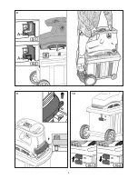
 (Fig. 2)

Scope of delivery

1x Instruction manual 
1x Spanner  
1x Silent shredder
1x Collection box 
1x Base frame   
2x Wheel set 
2x Support foot set 
1x Small parts bag
1x Adjusting knob   
1.  Take all parts out of the package. Be sure four pro-

truding supports in the bottom of the motor unit pass 

through four notches in the upper face of the base 

frame. (Fig. 3)

2.  Slide the collection box out of the base frame. (Fig. 4)

3.  Fit the front wheel sets to the base frame with the aid 

of two screws. (Fig. 5)

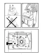
4.  Use the spanner to mount wheels to the base fame 

using two wheel shafts, two grommets, two spring 

grommets and two screws. Assemble cap by pushing 

in on by hand. (Fig. 6)

5.  Slide the collection box back to the base frame. En-

sure that the collection box runs above the guide rails. 

(Fig. 7) 

6.  Stand and put hands in position as shown in Fig. 8. 

Lay the motor unit on the base frame by placing four 

protruding supports (Fig. 8/Item B) of the motor unit 

on the slots (Fig. 8-1/Item A) of the base frame. 

Summary of Contents for GSLN 2600

Page 1: ...n funzione leggere le istruzioni perl utilizzo Istruzioni per l uso Traduzione delle istruzioni per l uso originali IT RU Navodila za uporabo Prevod originalnega navodila za uporabo Pred uporabo prebe...

Page 2: ......

Page 3: ...1 2 3 4 9 8 7 6 5 11 10 1 1...

Page 4: ...ne della distanza tra le lame 7 Contenitore di raccolta 8 Telaio 9 Piedi di supporto 10 Ruota 11 Interruttori di sicurezza SI Opis 1 za ita pred preobremenitvijo 2 stikalo za vklop izklop 3 stikalo za...

Page 5: ...3 2 3 4 5 7 6...

Page 6: ...4 8 10 9...

Page 7: ...5 11 12 13 6...

Page 8: ...zone de danger 4 En cas d endommagement du c ble retirez imm diatement la prise et proc dez au remplacement 5 Portez une protection visuelle et acoustique 6 Niveau acoustique mesur sur la base de la...

Page 9: ...ne gospodinjske odpadke Odnesite ga na ustrezno zbirno mesto ES 1 Lea las instrucciones antes de usar el aparato 2 Precauci n Herramienta de rotaci n el ctrica La herramienta contin a funcionamiento d...

Page 10: ...DE 4 Vorbereitung DE 5 Montage Ordnungsgem e Nutzung DE 5 Bedienelemente DE 5 Ein Aus Schalter Richtungsschalter berlastschutz Demontage DE 5 Zufuhr DE 5 Entleeren des Sammelbeh lters DE 6 Einstellen...

Page 11: ...chlages d Zweckentfremden Sie das Kabel nicht um das Ger t zu tragen aufzuh ngen oder um den Ste cker aus der Steckdose zu ziehen Halten Sie das Kabel fern von Hitze l scharfen Kanten oder sich bewege...

Page 12: ...iese Vorsichtsma nahme verhindert den unbeabsichtigten Start des Ger tes d Bewahren Sie unbenutzte Elektrowerkzeuge au erhalb der Reichweite von Kindern auf Lassen Sie Personen das Ger t nicht benutze...

Page 13: ...r Sie das Ger t von einem Arbeitsbereich zum andern bewegen 8 Stecken sie Ihre H nde nicht in den Einf llschacht und halten Sie sie fern von sich drehenden Klingen 9 Heben oder tragen Sie den Gartenh...

Page 14: ...heitsschalter nach oben dr cken Abb 10 1 Ordnungsgem e Nutzung Dieser H cksler ist f r das Schneiden von faserigen und holzhaltigen Gartenabf llen und f r deren Kompostie rung ausgelegt Bedienelemente...

Page 15: ...ersten Durchlauf zer quetscht und erst im zweiten geschnitten Zum L sen der Einstellschraube 6 die Schraube eine halbe Um drehung gegen den Uhrzeigersinn drehen 3 Nachdem Sie die Einstellung vorgenomm...

Page 16: ...e es umweltgerecht Geben Sie das Ger t bitte in einer Ver wertungsstelle ab Kunststoff und Metallteile k nnen hier getrennt und der Wiederverwertung zugef hrt werden Auskunft hierzu erhalten Sie auch...

Page 17: ...Controls GB 5 On off switch Reversing switch Overload protection Disassembling GB 5 Feeding GB 5 Emptying the collection box GB 5 Adjusting the cutting gear GB 5 Troubleshooting GB 6 The motor does n...

Page 18: ...e cord away from heat oil and sharp edges or moving parts of the tool Damaged or tangled cords increase the risk of electric shock e When operating a power tool outdoors use ex clusively extension cor...

Page 19: ...and clean Thoroughly maintained cutting tools with sharp cutting edges are jamming less often and are easier to guide g Use power tools accessories add on tools etc in accordance with these instructio...

Page 20: ...ed 19 If the insulation on a power cable or extension lead is found to be cut or damaged do not touch it Dis connect the power supply immediately and have the damaged cable replaced Do not repair dama...

Page 21: ...e material into the feeding tunnel Do not use your hands directly Keep the pusher well after use Only insert as much material as will not block up the feeding tunnel Chop garden waste that has been st...

Page 22: ...of rotation to the desired position after the shredder has come to a complete standstill GB 6 Care and maintenance WARNING Before commencing cleaning and maintenance procedures make sure the garden s...

Page 23: ...be ad ditionally retrieved via the consecutive serial number M nster 10 05 2013 Gerhard Knorr Technical Management Ikra GmbH Maintenance of technical documentation Gerhard Knorr K rcherstra e 57 DE 64...

Page 24: ...ssemblage Utilisation conforme FR 5 Commandes FR 5 Interrupteur On Off Commutateur de direction Protection contre la surcharge D sassemblage FR 5 Alimentation FR 5 Vidage du bac de collecte FR 6 R gla...

Page 25: ...ans liaison par c ble 1 S curit au poste de travail a Veillez la propret et au bon clairage de votre zone de travail Le d sordre ou le manque d clairage peuvent entra ner des accidents b N utilisez pa...

Page 26: ...upteur est d fectueux Un appareil qui ne peut plus tre allum ni teint est dangereux et doit tre r par c Retirez la fiche de la prise de courant et ou enlevez l accumulateur avant de proc der des r gla...

Page 27: ...ti res qui remontent par l entonnoir de remplissage 7 teignez le broyeur v g taux et attendez l arr t complet des lames avant de d placer l appareil d une zone de travail une autre 8 Ne placez jamais...

Page 28: ...ns de valorisation Commandes Interrupteur On Off Appuyez sur le bouton vert pour mettre la d chique teuse en marche Appuyez sur le bouton rouge pour l arr ter Remarque Cette machine est dot e d un int...

Page 29: ...utilisez une cl Allen pour tourner la vis d un demi tour dans le sens inverse des aiguilles d une montre 3 Suite l ajustage v rifiez que les lames broient ef ficacement Pour viter d endommager le bro...

Page 30: ...is s Votre commune ou l administra tion urbaine vous fourniront tous les renseignements ce sujet D claration de Conformit pour la CE Nous ikra GmbH Schlesier Stra e 36 D 64839 M nster Altheim d claron...

Page 31: ...ggio Utilizzo corretto IT 5 Controlli IT 5 Interruttore on off Interruttore di inversione Protezione da sovraccarico Smontaggio IT 5 Alimentazione IT 5 Svuotamento della scatola di raccolta IT 6 Regol...

Page 32: ...istruzioni si riferisce ad attrezzature elettriche alimentate dalla rete elettrica con cavo di rete ed attrezzature elet triche alimentate da accumulatore senza cavo di rete 1 Sicurezza del posto di...

Page 33: ...esa di corrente e o rimuovere l accumulatore prima di effettuare le regolazioni dell attrezzo di sostituire gli ac cessori o di riporre l attrezzo Questa misura precauzionale impedisce l accensione in...

Page 34: ...nersi lontano dalla lame rotanti 9 Non sollevare o trasportare mai il trituratore da giardi no a motore in funzione 10 Il trituratore pu essere fatto funzionare solo in posi zione verticale e non incl...

Page 35: ...odo tale da non permettere al motore di continuare a funzionare premere prima il pulsante rosso dell interruttore on off per arrestare il motore Quindi ruotare completamente l interruttore di inversio...

Page 36: ...enitore di raccolta 3 La quantit di materiale triturato accumulato non deve mai raggiungere il pozzo di espulsione del trituratore 4 Quando il contenitore di raccolta pieno spegnere il trituratore da...

Page 37: ...i Requisiti Essenziali di Sicurez za e di Tutela della Salute di cui alle Direttive 2006 42 CE Direttiva Macchine 2004 108 CE direttiva EMV 2011 65 EU direttiva RoHS e 2000 14 CE Direttiva sul la rumo...

Page 38: ...ca ES 4 Preparaci n ES 5 Ensamblaje Uso correcto ES 5 Mandos y controles ES 5 Interruptor On off Interruptor cambio rotaci n Protecci n por sobrecarga Desmontaje ES 5 Alimentaci n ES 5 Vaciado del rec...

Page 39: ...icas en am bientes bajo peligro de explosi n donde haya l quidos gases o polvos combustibles Las herramientas el ctricas producen chispas que pueden incendiar el polvo o los vapores c Al usar la herra...

Page 40: ...o a depositar el aparato en alg n lugar Esta medida preventiva evita que se ponga en marcha el aparato de una forma inadvertida d Guarde las herramientas el ctricas que no se utilicen fuera del alcan...

Page 41: ...a desfibradora si est tum bada en el suelo 11 No alimente la biotrituradora con objetos extra os ta les como piedras vidrio metal tierra o pl sticos 12 Apague y desconecte el aparato de la corriente e...

Page 42: ...rco de la base mediante la coloca ci n de cuatro soportes salientes Fig 8 Item B de la unidad de motor en las ranuras Fig 8 1 Item A de la bancada 7 Fije la placa de ubicaci n para el bastidor de base...

Page 43: ...vuelta 2 Si usted est de triturando materiales pesados como los materiales m s fuertes o grandes puede ser necesario pasar por la trituradora dos veces para aplastar el material antes de cortar por c...

Page 44: ...ecializado separando las piezas del pl stico y de metal La informaci n referente a la disposici n de materiales y los dispositivos est n dis ponibles de la su administraci n local EC Declaraci n de co...

Page 45: ...GR 1 ELLHNIKA 1 7 GR 2 GR 2 GR 3 GR 4 GR 5 GR 5 GR 5 On off GR 5 GR 5 GR 6 GR 6 GR 6 GR 6 GR 7 GR 7 GR 7 K GR 7 GR 7 GR 7...

Page 46: ...1 a b c 2 a b c d e GR 2 GSLN 2600 V 230 240 Hz 50 W 2600 rpm 40 mm 40 kg 28 dB A 75 1 K 3 0 EN 13683 Service life S6 40 full load 4 min no load 6 min I IPX4 ProdSG 80 dB A...

Page 47: ...GR 3 f 3 a b c d e f g 4 a b c d e f g 5 a 1 2 3...

Page 48: ...GR 4 4 1 2 3 4 5 6 7 8 9 10 1 2 3 4 5 6 7 8 9 10 11 12 13 14 15 8A 16 15 1 5 mm2 15 40 2 5 mm2 17 18 19 20 21 22 If the MAINS IMPEDANCE Zmax 0 376 OHM...

Page 49: ...GR 5 230 240V AC 50Hz 30 mA 2 1x 1x 1x 1x Collection box 1x 2x 2x 1x 1x 1 3 2 4 3 5 4 6 5 7 6 8 8 B 8 1 A 7 9 8 10 1 On off 1 Nr 2 A 1 A A B 1 B on off on off on off on off 1 reset on off 11...

Page 50: ...GR 6 a ON OFF b c d 13 B 0 0 75 mm A 13 6 1 2 6 3 1 2 3 4 On Off B reset on off A B B...

Page 51: ...S 2000 14 EK K EN 60335 1 2002 A11 A1 A12 A2 A13 06 42 EC Annex I 05 06 EN 13683 2003 A1 EN 62233 2008 ZEK 01 2 08 12 08 EN 55014 1 2006 A1 EN 55014 2 1997 A1 A2 EN 61000 3 2 2006 A1 A2 EN 61000 3 11...

Page 52: ...ilna uporaba SI 5 Upravljanje SI 5 Stikalo za vklop izklop Stikalo za preklop delovanja v drugo stran Za ita pred preobremenitvijo Razstavljanje SI 5 Vlaganje materiala SI 5 Izpraznitev zbirne posode...

Page 53: ...okroto Vdor vode v elektri no napravo zvi a tveganje za udar elektri nega toka d Kabla ne uporabljajte za druge namene npr za no enje ali obe anje naprave ali za vle enje vti a iz vti nice Kabel zavar...

Page 54: ...lite Elektri no orodje je nevarno e ga uporabljajo neizku ene osebe e Napravo skrbno negujte Kontrolirajte e premikajo i deli naprave brezhibno delujejo in se ne zatikajo e so deli naprave odlomljeni...

Page 55: ...sekljalnika 13 e vrtni sekljalnik pri ne nenormalno vibrirati ga takoj izklopite 14 Vsi ro aji in oprimki morajo biti isti in suhi Pred uporabo sekljalnika preglejte vse vijake matice zapahe in druge...

Page 56: ...i Vlaganje materiala Material k ga elite sesekljati vstavite na desni strani vlagalne odprtine Material bo rezilo samodejno vleko v stroj Pozor Dalj i material ki vstavite v stroj lahko zaradi premika...

Page 57: ...sekljalnik Material izvlecite iz vlagalnega dela Debelej e palice potisnite v stroj tako da jih no i ne zagrabijo takoj Rezilni no i so blokirani Stikalo za delovanje v drugo stran prestavite v polo a...

Page 58: ...no ugotovljivo na podlagi zaporedne serijske tevilke M nster 10 05 2013 Gerhard Knorr Tehni no vodstvo Ikra GmbH Shranjevanje tehni nih dokumentov Gerhard Knorr K rcherstra e 57 DE 64839 M nster Garan...

Page 59: ...RU 1 1 7 RU 2 RU 2 RU 3 RU 5 RU 5 RU 5 RU 5 RU 5 RU 6 RU 6 RU 6 RU 6 RU 7 RU 7 RU 7 RU 7 RU 7 RU 8...

Page 60: ...RU 2 GSLN 2600 230 240 50 2600 40 40 28 75 1 K 3 0 EN 13683 S6 40 4 6 I IPX4 ProdSG 80 1 a b c 2 a b c d e...

Page 61: ...RU 3 3 a b c d e f g 4 a b c d e f g 5 a 1 2 3 4...

Page 62: ...RU 4 1 2 3 4 5 6 7 8 9 10 1 2 3 4 5 6 7 8 9 10 11 12 13 14 15 8 16 17 15 1 5 mm2 15 2 5 mm2 18 19 20 21 22 23 Zmax 0 376 GSL 2800...

Page 63: ...230 240V 50Hz RCD 30 A 2 1 1 1 1 1 2 2 1 1 1 3 2 4 3 5 4 6 5 7 6 8 8 8 1 7 9 8 10 1 A 1 A A B 1 B 1 RU 5...

Page 64: ...RU 6 11 a b 10 2 c d 13 B 0 mm 0 75 mm A 13 6 1 2 6 3 1 2 3 4 On Off A RCD...

Page 65: ...00 14 EC EN 60335 1 2002 A11 A1 A12 A2 A13 06 42 EC Annex I 05 06 EN 13683 2003 A1 EN 62233 2008 ZEK 01 2 08 12 08 EN 55014 1 2006 A1 EN 55014 2 1997 A1 A2 EN 61000 3 2 2006 A1 A2 EN 61000 3 11 2000 8...

Page 66: ...24 12 RU 8...

Page 67: ......

Page 68: ...1 Aharnes Tel 30 210 2402020 Fax 30 210 2463300 HR VAR ERCO d o o Stipana Vilova 14A 10090 ZAGREB Tel 385 91 571 3164 Fax 385 1 3430 820 HU Tooltechnic Kft Nagyt t nyi t 282 1225 Budapest Tel 36 1 330...

Reviews: