Ikegami MKC-310HD Operation Manual Download Page 3


Safety Precautions


For Safe and correct usage 

Thoroughly read the “Safety Precautions” and the 

operation manual before using the unit. Keep them 

carefully after reading and use as ready reference. 


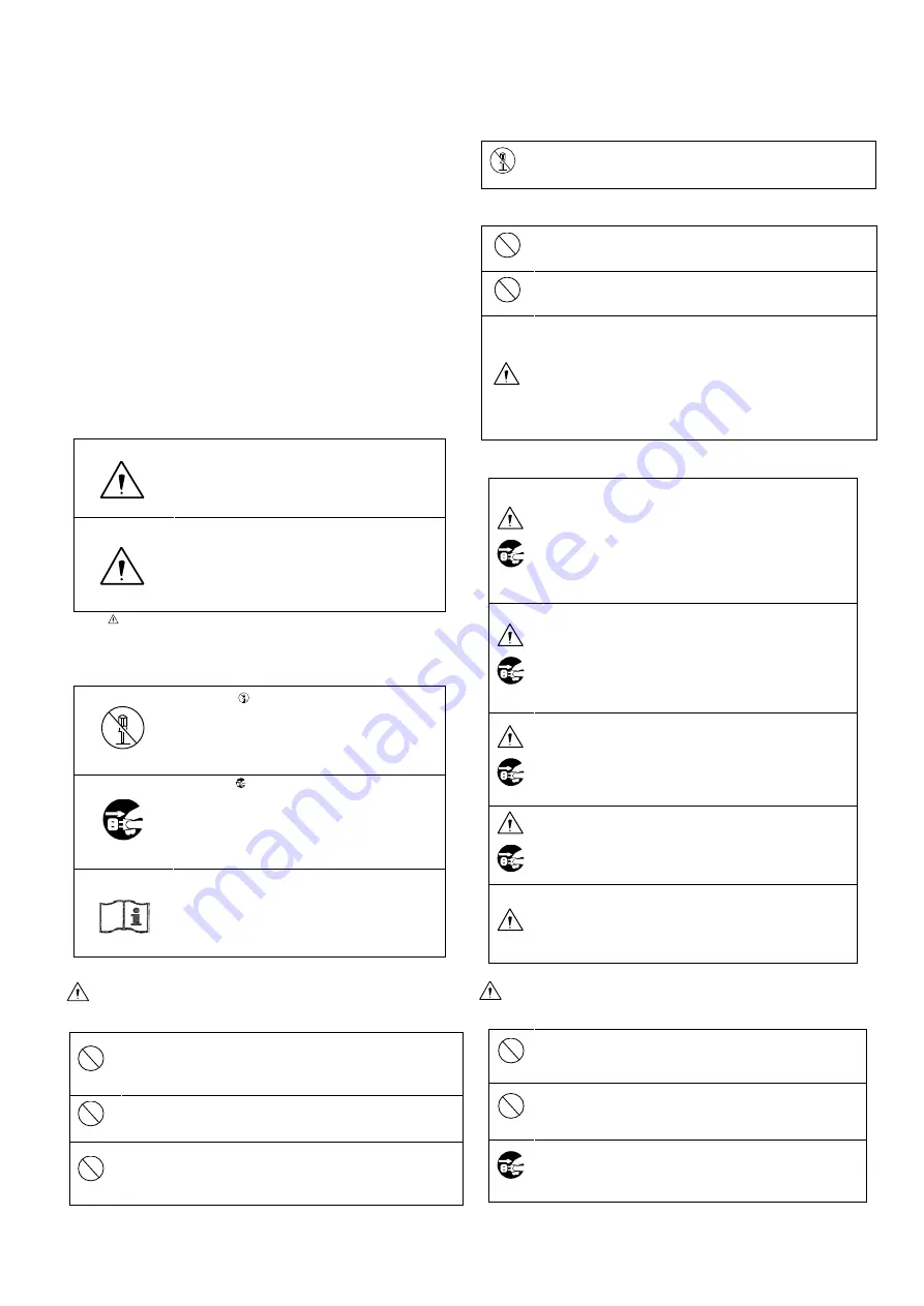
Pictorial Symbols 

The “Safety Precautions” and markings on the product 

contain various pictorial symbols to assure the safety 

use  of  the  product  and  prevent  an  injury  to  you  and 

other persons as well as property damage. 

As each symbol has the following meanings, thoroughly 

under- stand them before using the unit. 

Please note that some precautions may not be 

applicable to the product that you purchased 


WARNING: 


Indicates a potentially hazardous 

situation that may arise due to 

improper handling by taking no notice 

of this symbol and could result in a 

serious injury or death. 

CAUTION: 


Indicates a potentially hazardous 

situation that may arise due to 

improper handling by taking no notice 

of this symbol and could result in an 

injury or property damage only.


  (Note) : This symbol attracts your attention. 


Examples of symbols 


Symbol “ ” means a prohibited action.   

The content of prohibited matter is 

mentioned near or in the figure. (The 

figure on the left side represents “Caution 

for disassembling”.


Symbol “ ” means a mandatory or 

directive content. Practical precautions 

are shown in the figure. (The figure on 

the left side represents “Pull out power 

plug from plug outlet.”)


This mark is a symbol of an operator to 

advise the annex. 


WARNING 

When using the unit:


Do not place a receptacle containing water or a 

small metallic piece on the unit!   

  If water spills in the unit, a fire or electric shock 

may be   

caused.


Do not use other power supply voltage than 

specified!   

  A fire or electric shock may be caused.


Do not put a metal body or flammable material into 

the opening of the unit!   

  Do not drop in such material!     

  A fire or electric shock may be caused.


Do not make alterations to the unit!   

  A fire or electric shock may be caused. 

 
When installing the unit: 


Do not set the unit in an unstable place!   

  It may drop or turn down, causing an injury. 


Do not connect to any other equipment than specified!   

  A fire or electric shock may be caused.


When it is installed, please contact the dealer or 

salesman.! 

When fixing the unit, do so in accordance with the 

specified procedure; otherwise it may drop or 

turn down, causing a fire, electric shock or 

injury. 

Especially when fixing it to the wall or ceiling, 

be sure to ask the dealer or salesman.


When an abnormal state occurs: 


If the unit produces smoke, gives out a foul 

smell or produces an abnormal sound, turn off 

the power switch immediately and pull out the 

power plug! 

If the unit is used as it is, a fire or electric 

shock may be caused. Check that no smoke is 

produced, and then contact the dealer or sales 

representative. 


If water or foreign matter enters the unit, turn 

off the power switch and pull out the power 

plug!     

If the unit is used as it is, a fire or electric 

shock may be caused. Check that no smoke is 

produced, and then contact the dealer or sales 

representative. 


If the unit is dropped or the case is broken, turn 

off the power switch and pull out the power 

plug!   

If the unit is used as it is, a fire or electric 

shock may be caused. Contact the dealer or 

sales representative. 


If the unit fails to operate properly, turn off the 

power switch and pull out the power plug!     

If the unit is used as it is, a fire or electric 

shock may be caused. Contact the dealer or 

sales representative. 


Do not use any damaged power cord (exposed 

core, broken wire, etc.)!   

If the unit is used as it is, a fire or electric 

shock may be caused. Contact the dealer or 

sales representative. 


CAUTION


When using the unit: 


Do not place a heavy thing on the unit! 

The unit may lose a balance or drop, causing an 

injury.


Do not get a leg over the unit or carrying case!   

Do not sit down on it! 

The unit may break down or turn down, causing 

an injury. 


Before relocating it, always turn off the power switch, 
remove the power plug, and disconnect the cables 
connected among equipment! 

If a cord is damaged, a fire or an electric shock might 

Summary of Contents for MKC-310HD

Page 1: ...1 MKC 310HD Rev A Digital Process Compact 3CMOS Color Camera Operation Manual...

Page 2: ...2 The software that we have manufactured is copyrighted by IKEGAMI TSUSHINKI CO LTD You may not reproduce or alter it in whole or in part without permission...

Page 3: ...the unit Do not set the unit in an unstable place It may drop or turn down causing an injury Do not connect to any other equipment than specified A fire or electric shock may be caused When it is ins...

Page 4: ...ions not expressly approved by the party responsible for compliance could void the user s authority to operate the equipment About Camera Cable Note the following While removing the camera cable from...

Page 5: ...15kV air 8kV contact 15kV air Floors should be wood concrete or ceramic tile If floors are covered with synthetic material the relative humidity should be at least 30 Electrical fast transient burst...

Page 6: ...ion from structures objects and people a Field strengths from fixed transmitters such as base stations for radio cellular cordless telephones and land mobile radios amateur radio AM and FM radio broad...

Page 7: ...election 21 4 Menu Operation 23 4 1 Operation Method 23 4 2 Video Adjust 24 4 3 AE Mode 25 4 4 Detail 28 4 5 Video Setting 29 4 6 Picture Setting 31 4 7 Scene File 32 4 8 Foot Switch 33 4 9 White Bala...

Page 8: ...ing 44 5 4 2 For cards on which recording is nished 44 5 5 3D support function 45 5 5 1 Connection and setting 46 5 5 2 Linkage the operation panel and the menu 46 6 Default Settings 47 7 Specificatio...

Page 9: ...ration theatre light especially Endoscopy It performs 1920x1080 Full HDTV format with 1000TV lines horizontal resolution F10 2000lx of sensitivity S N ratio with 54dB MKC 310HD realizes miniaturizatio...

Page 10: ...ages 15 16 BARS button Output an internal color bar signal of the camera to a color monitor Can be used to adjust the color monitor brightness contrast etc See page 18 FREEZ button Possible to freeze...

Page 11: ...size of the camera connector differs on the camera head side and CCU side DVI D Output Connector Connects with DVI D input monitor etc A DVI D cable optional is required for connection HD SDI Output...

Page 12: ...0Base T 100Base TX For connection with other devices please connect a cable of category 5 or higher SD CARD This is the insertion port for the SD card The SD card is not included in the equipment spec...

Page 13: ...ed data may be damaged lost please note we assume no responsibility for damage and so on caused by data corruption and so on When an SD card is used improperly When an SD card is not properly inserted...

Page 14: ...to this device it conforms to the IEC60601 1 2005 Equipment connected to this unit except FOOTSW that conform to IEC standards that apply to the equipment or IEC60601 1 2005 If you are connecting to a...

Page 15: ...ame MPU51 105 P01J For exclusive camera head connection goods Using heads other than that speci ed may result in failure The operator must not touch a connector simultaneously with a patient DVI conne...

Page 16: ...ast use When power is turned off in the state of still screen picture that state will not be held even if power is turned on again and MKC 310HD is set to the normal shooting state When moving the CCU...

Page 17: ...17 3 3 Setting White Balance...

Page 18: ...18 3 4 Adjustment PAINT...

Page 19: ...19 3 5 Adjustment AE Level...

Page 20: ...20 3 6 Adjustment Auto Gain 3 7 Freeze output...

Page 21: ...21 3 8 Color bar output...

Page 22: ...22 3 9 Scene File Selection...

Page 23: ...e is mounted 2 The Recorder item is only displayed if the optional module is mounted 2 Use the keys on the front of the CCU to select the item and then press the SET button to enter the submenu screen...

Page 24: ...he same function as paint adjustment volume on the front of the CCU 128 to 127 Increasing the value causes blue to be displayed more vividly White shading White shading function setting ON Carries out...

Page 25: ...is carried out in the item entitled Manual Shutter Manual Shutter The shutter speed when Shutter Control is FIX is set here If set to AUTO it is ignored It is usually used in the OFF setting OFF The s...

Page 26: ...tering Area Select Possible to adjust the extent of a metering area Carries out automatic adjustment of the shutter and gain etc based on the image in the frame displayed in the screen MID About 40 of...

Page 27: ...he sensitivity Although the sensitivity will increase by a factor of two horizontal resolution will be slightly lower ON Carries out increase the sensitivity OFF Does not carry out increase the sensit...

Page 28: ...adjust the detail enhancement level 128 to 127 Increasing the value results in a sharper image Boost Frequency Set the boost frequency for the detail enhancement 2 MHz to 28 MHz The lower the value th...

Page 29: ...ve signal 1080i Output the interlace signal DVI Setting Select the DVI output signal output format 1080p Output the progressive signal 1080i Output the interlace signal Gamma If gamma correction is ca...

Page 30: ...or intensity 64 to 63 The higher the value the more intense the color The lower the value the more faded the color With 64 it is monochrome Genlock Mode Select the Genlock mode Auto When GENLOCK signa...

Page 31: ...ation output V Flip Sets the vertical inversion of the image ON Inverts to a vertical direction for output OFF The vertical direction becomes the normal rotation output Digital Zoom Magnification sett...

Page 32: ...tting Description Scene Number Select and read the set scene file Store Scene Store the set condition in the scene file Select the scene file you wish to set and press the SET button Initialize Scene...

Page 33: ...CENE FILE Switches the scene file selection H FLIP Outputs a horizontally inverted image V FLIP Outputs a vertically inverted image ROTATE Outputs an image inverted 180 degrees ZOOM IN Carries out ele...

Page 34: ...nual adjustment of white balance Adjustment is carried out with Manual Gain Red Blue ATW Automatically adjusts to the white balance in relation to pick up conditions Manual Gain Red Adjusts the red ga...

Page 35: ...ion method SNAPSHOT Compress with JPEG method and record on the SD card STREAMING Compress with the H 264 method and distribute the image JPEG Quality Sets the image quality if the compression method...

Page 36: ...select OK To stop press Cancel and then press the Set button Only displayed if the IP address is changed Note The Setting values such as IP address and sub net mask will vary according to the network...

Page 37: ...ain by this device disruption due to unauthorized access system halt and so on The messages include the following but please implement sufficient other measures under your own responsibility Do not in...

Page 38: ...F It disables the automatic folder creating function Media Select It selects the recording media to be preferentially used SD CARD The SD card is preferentially used for recording USB Storage The USB...

Page 39: ...enu Lock Menu lock ON Sets a state in which no settings other than Menu Lock can be changed During MENU LOCK a red lock mark is displayed in the upper right of the menu screen OFF Sets to a state in w...

Page 40: ...y the software version of this camera 1 Only displayed if IP ENC module is mounted 2 Only displayed if Recorder module is mounted Version Information Quit CCU Firmware V5 00 CCU FPGA V5 00 Head FPGA V...

Page 41: ...If SYNC is input to the GENLOCK terminal the camera automatically switches from internal synchronization to external synchronization SYNC input condition 3 value SYNC 0 6 Vp p 75 Ohms 5 1 1 Wiring co...

Page 42: ...Frame You can change the range of a metering frame as desired By adjusting a metering frame a video can automatically be adjusted in keeping with the use environment 5 2 1 Setting Select AE Mode Area...

Page 43: ...T button to complete adjustment Size Setting Select Size and press the SET button to adjust the size of a metering frame The upper left corner of the frame is xed The lower right corner can be moved f...

Page 44: ...then press the SET button The selected scene is immediately initialized 5 3 3 Setting of Scene File To use the stored scene le operate the front panel See page 3 8 Scene File Selection21 or the foot s...

Page 45: ...setting various kinds of camera functions simultaneousness of left and right and adjust easily when 3D system is constructed using this two machines Coaxial cable CCU Master CCU Slave Video output ca...

Page 46: ...tion of the output of the left and right of the camera 3 Turn ON the main power switch It s possible even from the left or right of the CCU 4 From MENU please select by a cursor in the order of Video...

Page 47: ...ite Shading READY D Range Expansion NORMAL Flare Control 17 AE Mode Shutter Control AUTO Manual Shutter OFF Auto Shutter Limit 1 10000 AE Level 0 AE Speed MID Peak Ratio 20 Area Select MID Gain Contro...

Page 48: ...Genlock Mode AUTO GenLock H Phase 0 GenLock V Phase 0 3D Support SLAVE Picture Setting DNR ON DNR LEVEL 8 H Flip OFF V Flip OFF Digital Zoom x1 0 Picture Shift H 0 Picture Shift V 0 R DPC ON Scene Fil...

Page 49: ...Manual Gain Blue 64 IP ENC Setting IP Address 192 168 001 100 Subnet Mask 255 255 255 0 Encoder Mode SNAPSHOT JPEG Quality A Recorder Setting Auto Folder ON Media Select SD CARD Miscellaneous Center M...

Page 50: ...ing Transport Atitude 2000m or less 14 Operating Transport Storage Relative Humidity 0 to 90 No moisture condensation 15 Transport Storage Atmospheric pressure 700hPa to 1060hPa 16 Dimensions Weight C...

Page 51: ...ime The error message of Snapshot Message Mean REC ERR 01 Not snapshot mode Mode of CCU IP ENC is not a snapshot REC ERR 02 No SD Card SD card is not inserted in the CCU The IP ENC does not recognize...

Page 52: ...52 8 External Appearances 8 1 Camera Head 8 2 CCU...

Page 53: ...Tsushinki Co Ltd Marchi 2017 Ikegami Tsushinki Co Ltd All rights reserved Reproduction or duplication without permission of Ikegami Tsushinki Co Ltd of editorial or pictorial content in whole or in p...

Page 54: ...54...

Reviews: