9VX3
SECTION 2 STRUCTURE AND FUNCTION
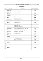
TABLE OF CONTENTS
Subject
page
Hydraulic S y s te m .....................................................................................................
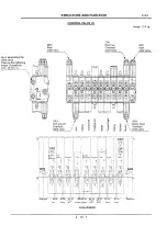
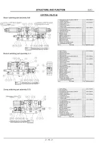
Control V alve.............................................................................................................
2 -1 0 -1
Swing Drive Device & B earing...............................................................................
2 -1 1 -1
Swing Motor A ss’y ....................................................................................................
2 -1 2 -1
Rotary Joint and Lower Piping A ss’y ....................................................................
2 -1 3 -1
Travel Motor and Reduction Gear A ss’y ...............................................................
2 -1 4 -1
Crawler Shoe Adjusting D e v ic e .............................................................................
2 -1 5 -1
Front Idler A ss’y ........................................................................................................
2 -1 6 -1
Lower Roller A ss’y....................................................................................................
2 -1 7 -1
Upper Roller A ss’y ...................................................................................................
Rubber Crawler Shoe A ss’y ....................................................................................
2 -1 9 -1
Remote Control V a lv e ..............................................................................................
Block Valve Ass’y .....................................................................................................
Travel Speed Shift Valve A ss’y ..............................................................................
2
-
2 2 - 1
Hydraulic C ylin d e rs..................................................................................................
2
-23-1
Attachm ent A ss’y .....................................................................................................
2 -24-1
Bucket A ss’y ..............................................................................................................
2 -25-1
Attachm ent D a te .......................................................................................................
2 -26-1
OK Monitor A ss’y .....................................................................................................
Electrical Wiring and Locations..............................................................................
2 -28-1
Electrical Wiring System Diagram ..........................................................................
2 -29-1
Summary of Contents for 9VX3
Page 1: ...Service Guide 9VX3 I H I SERIAL NUMBERS WB004001 up PUB No 1 1205...
Page 21: ...Swing motor...
Page 34: ...A 1 34 6 7 14 15 17 18 10 19 20 25 23 13 35 SECTION...
Page 38: ...3 1 0 Disassembly drawing For part names and numbers refer to the parts catalog...
Page 45: ...Boom Cylinder head details...
Page 51: ...Boom Swing Tightening torque 176 N m M16 x 1 5 19 8 7 6 13 5 DETAIL P DETAIL H...


