background image


STEP 1.

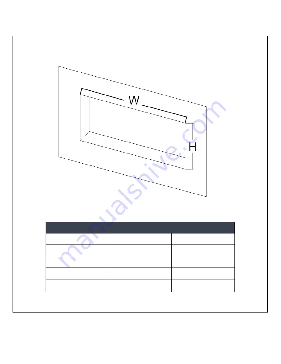
 Select a dry wall to open a hole for the fireplace. Recess opening may be found in the 

chart below: 


Recess Opening Dimensions 

Model Number 

Width 

Height 

INTU 36 

  34.19

"

 (869CM) 

22.28

"

 (56.59CM) 

INTU 50 

48.19

"

 (122.4CM) 

22.28

"

 (56.59CM) 

INTU 60 

58.19

"

 (147.8CM) 

22.28

"

 (56.59CM) 

INTU 72 

70.19

"

 (178.28CM) 

22.28

"

 (56.59CM) 


RECESSED TO WALL INSTALLATION


Figure ( A ) 

Summary of Contents for INTU 36

Page 1: ...s product Failure to do so could result in fire electric shock or serious personal injury CAUTION Keep this owner s manual for future reference If you sell or give this product away make sure this manual accompanies this product IGNIS INTU Recessed Electric Fireplace Model INTU 36 INTU 50 INTU 60 INTU 72 OWNER S MANUAL ...

Page 2: ...r damage the fireplace To prevent a possible fire DO NOT block air intakes or exhaust in any manner Doing so could cause a fire DO NOT use on soft surfaces like a bed where openings may become blocked The fireplace has hot and arcing or sparking parts inside DO NOT use it in areas where gasoline paint or flammable liquids are used or stored Use this fireplace only as described in this manual Any o...

Page 3: ...f it has not occurred with the use of other appliances iii During use check frequently to see if the plug outlet or face plate is HOT iv If the outlet or face plate is HOT discontinue use immediately and have a qualified electrician inspect and or replace the faulty outlets The power cord supplied with the fireplace has three prongs two flat blades live and neutral and one round pin ground If a 3 ...

Page 4: ...imension PRODUCT DIMENSIONS Model Number A B C D E F G INTU 36 36 915CM 21 46 54 4CM 33 63 855CM 5 86 14 9CM 31 788CM 11 69 297CM 5 03 128CM INTU 50 50 127CM 21 46 54 4CM 47 63 121CM 5 86 14 9CM 45 114 3CM 11 69 297CM 5 03 128CM INTU 60 60 152 4CM 21 46 54 4CM 57 63 146 4CM 5 86 14 9CM 55 139 7CM 11 69 297CM 5 03 128CM INTU 72 72 183CM 21 46 54 4CM 69 6 177CM 5 86 14 9CM 67 04 170 3CM 11 69 297CM ...

Page 5: ...ct a suitable location that is not susceptible to moisture and is away from drapes furniture and high traffic areas NOTE Follow all National and local electrical codes MINIMUM CLEARANCE TO COMBUSTIBLES Measurements are taken from the glass front Bottom 0 Top 8 300mm to mantel Sides 0 Top 8 300mm to ceiling Back 0 MINIMUM MANTEL CLEARANCES WARNING WHEN USING PAINT OR LACQUER TO FINISH THE MANTEL TH...

Page 6: ...ening may be found in the chart below Recess Opening Dimensions Model Number Width Height INTU 36 34 19 869CM 22 28 56 59CM INTU 50 48 19 122 4CM 22 28 56 59CM INTU 60 58 19 147 8CM 22 28 56 59CM INTU 72 70 19 178 28CM 22 28 56 59CM RECESSED TO WALL INSTALLATION Figure A ...

Page 7: ...the fireplace to a soft clean place using the screwdriver to take off the TWO screws in both sides Figure B STEP 3 Have two people to pull the trim up then take them out of the fireplace box Figure C Figure B Figure C ...

Page 8: ...8 STEP 4 Using the screwdriver take off the 8 screws as in above Figure D Have two people take out the glass panel as in Figure E and move it to a clean soft place to avoid scratching Figure D Figure E ...

Page 9: ...he FOUR wall screws in each side of the fireplace box Figure F STEP 6 Place the decorative crystals For crystals ember installation please refer to Page 10 Move and replace the glass panel and metal trim with screws Fireplace when finished will appear as below Figure G Figure F Figure G ...

Page 10: ...removing the screws refer to Figure 1 D Mark out location then mount the bracket s onto the wall using the supplied screws This bracket MUST have the hooks facing upward and be level E With the wall mounting bracket installed have two people lift the appliance up and insert the two hooks on the bracket into the two slots on the back of the appliance F Check the appliance for stability ensuring tha...

Page 11: ... behind the cover plate that has been removed as shown above 3 Remove the new cover plate found in the hardware bag Punch out the 7 8 22 2mm hole and install a box connector through the void into the junction box Snap the box connector clamp onto the supply wires 4 Referring to figure 3 and using the wire connectors first connect the green ground wires together G Then connect the white neutral wir...

Page 12: ...ystal media set please note that the crystal or pebble media may have a fine oil residue that needs to be cleaned prior to installation Clean them with mild dish soap drain rinse thoroughly and dry before placing into the tray D Place the plastic tray I into the fireplace s designated place Then carefully place crystal or pebble set into the bottom tray on the front of the appliance as illustrated...

Page 13: ...eplace see figure below or by the battery powered REMOTE CONTROL The operation and functions of the two methods are the same Before operating please review the IMPORTANT SAFETY INFORMATION on Pages 2 and 3 and heed all warnings Remote Control Control Panel Operation BUTTON FUNCTION ACTION INDICATION POWER ON Enables control panel functions and remote control Turns on flame effect OFF Disables cont...

Page 14: ... air for 10 seconds to allow heater to cool down then turns off NOTICE When the heater is first turned on a slight odor may be present This is normal and should not occur again unless the heater is not used for a long period of time NOTICE To improve operation aim the remote control at the front of the fireplace DO NOT press the buttons too quickly Give the unit time to respond to each command Tem...

Page 15: ...a vacuum or duster to remove dust and dirt from the heater and vent areas Plastic Wipe gently with a slightly damp cloth and a mild solution of dish soap and warm water NEVER use abrasive cleansers liquid sprays or any cleaner that could scratch the surface Maintenance Risk of electric shock DO NOT OPEN any panels No user serviceable parts inside ALWAYS turn the appliance OFF and unplug the power ...

Page 16: ...16 Ignis Development Inc 409 Joyce Kilmer Ave Unit 5B New Brunswick NJ 08901 1 855 694 4647 info ignisproducts com ...

Reviews: