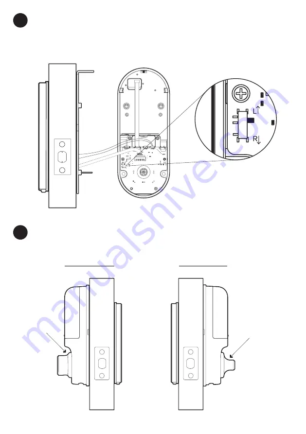
background image

15

Set the toggle to ‘

L

’ for 

left-hand installation 

Set the toggle to ‘

R

’ for 

right-hand installation

Connect Assembly Cable

Connect the sensor cable to the Back Assembly then connect the assembly cable from the 

Front assembly through the 54mm (2.12”) hole to the Back Assembly. Ensure that the wire 

is installed properly and securely. 

Fit Back Assembly to the Door Tailpiece

Ensure thumbturn position is turned to ‘unlock’ position.

Thumbturn 

is in vertical 

position

Thumbturn is 

in horizontal 

position

Assembly 

Cable

7

8

Right-hand Installation

Left-hand Installation

Door Sensor

Cable

Summary of Contents for IoT Deadbolt

Page 1: ...1 Version 0 3 09 21 Installers User guide IoT Deadbolt...

Page 2: ...this manual Please refer to our website iglooworks co support for the latest version of the manual Welcome This guide will get you up and running with your IoT Deadbolt In the meantime you should fol...

Page 3: ...nstallation 7 Prepare Lock for Installation 9 Installation Instructions 10 Test Lock 18 Prepare the Door Frame 19 User Guide Lock Anatomy 20 Features 22 Unlocking and Locking 23 Lock Pairing Provision...

Page 4: ...60mm 2 3 8 bac kset 70mm 2 3 4 backset Centerline 10mm Optional 54mm Door Thickness Drill for Drill for 35mm 1 3 8 Drill for 45mm 1 3 4 Drill for 60mm 2 3 8 Drill for 70mm 2 3 4 backset 60mm 2 3 8 bac...

Page 5: ...aterial AI Zinc Alloy ABS Weight Net 1 7kg Gross 2 2kg Unlock Mechanism Bluetooth PIN code Physical Keys Thumbturn Front Back Side 148mm 5 83 63mm 2 48 58mm 2 28 76mm 2 99 185mm 7 28 DO NOT USE Heavy...

Page 6: ...nGuide 148mm 5 83 185mm 7 28 Requirements Measurements 43mm 1 69 to 60mm 2 36 10mm 0 39 20mm 0 78 110mm 4 33 for 60mm 2 38 120mm 4 72 for 70mm 2 75 backset 50mm 1 96 a b c d e a b b b c e d Clearance...

Page 7: ...ure if your door is suitable send us web links to your door pictures to info iglooworks co PrepareDoorforInstallation Itemsneeded Recommended Door and door frame material Wood Recommended Gap between...

Page 8: ...entre of door edge Please ensure this chiseled surface is flattened with a depth of 2 7mm Door edge Fold here before drilling holes for side Chiselling Put the bolt tongue in chisel around the edge 54...

Page 9: ...for Left Right Hand Installation Set the toggle to R for right hand installation Right Hand Installation Set the toggle to L for left hand installation Hinge is on your left Hinge is on your right Le...

Page 10: ...t length you should use measure the distance x between the center of 54mm 2 12 hole to door edge Prepare bolt assembly based on the distance x Bolt ships with bolt assembly in 60mm 2 38 position If re...

Page 11: ...iece It is advisable to lubricate the hole before inserting the tailpiece Please ensure the bolt assembly is positioned horizontally insde the door Please ensure the front assembly is positioned strai...

Page 12: ...from the door Door thickness mm Notches to cut from the tip 60 3 55 4 50 5 45 6 Notch The recommended tailpiece protrusion from the door is 15mm 0 6 Screws 40mm 1 57 d Secure the Front Assembly using...

Page 13: ...ation Use the 2 x 4mm 0 16 screws to secure the door sensor to the back plate Screws 4mm 0 16 Right hand Installation Left hand Installation e e e 5 Do not overtighten the screws Please choose the sui...

Page 14: ...Fit in the Rubber Gasket Insert the front assembly cable through the rectangular hole on the rubber gasket The hole should be on the right side of the rubber gasket AssemblyCable Door Sensor Cable go...

Page 15: ...embly cable from the Front assembly through the 54mm 2 12 hole to the Back Assembly Ensure that the wire is installed properly and securely Fit BackAssembly to the DoorTailpiece Ensure thumbturn posit...

Page 16: ...tions module from the top of the unit On the bottom of the communications module you ll see a SIM card sticker label and a SIM card slot Insert your SIM card into the SIM card slot following the SIM c...

Page 17: ...ase ensure the ribbon is spread across the battery compartment for easier battery removal in the future It is optional to secure the battery cover further with the additional screw 11 Screws 6mm 0 24...

Page 18: ...installed Proceed to next steps Bummer Does the bolt lock and unlock when you turn the thumbturn Yes Left Right toggle incorrectly set No Tailpiece and or thumbturn incorrectly set Troubleshoot Try S...

Page 19: ...ongue locks then drill a corresponding hole on door frame Chisel to fit the strike plate in as well Mark Drill Hole Secure strike plate housing and strike plate using 2x 22mm 0 87 wood screws Affix th...

Page 20: ...0 Front BackAssembly Touch Screen Keypad Unlock Key hole Cover Remove cover to access physical key unlock 9V Jumpstart Clear Thumbturn Downlight LED LED Indicator User Guide Lock Anatomy Battery Cover...

Page 21: ...tery must be aligned with the 2 contact points on the IoT Deadbolt for 2 seconds Manual Locking Hold the Unlock button for 1 second to manually lock the IoT Deadbolt It also can be locked by manually...

Page 22: ...or update logs Security Lockout Be assured with an additional layer of security with the keypad lockout if the keypad is being tampered User can configure number of incorrect attempts to trigger lock...

Page 23: ...umbturn at the back of lock Auto Lock Works only with the Re lock Sensor Physical Key Use the physical key to lock the door Unlock Key Press and hold Unlock Thumbturn Use thumbturn at the back of lock...

Page 24: ...rk registration process can be initiated If specific settings are required by your IoT network provider you can specify this in Manual settings Otherwise you can proceed with Automatic connection set...

Page 25: ...e Physical key and Bluetooth Unlock can be used to unlock in this mode 1stTime 2ndTime 3rd and ConsecutiveTime 30 Sec 60 Sec 90 Sec 1 Min 5 Min 10 Min Triggered SecurityAlarm KeypadLockout 5 consecuti...

Page 26: ...ll hear a series of beeps and the keypad will light up 2 While holding the 9V battery to the jumpstart key in your PIN code on the keypad followed by the Unlock icon Please ensure terminals of the 9V...

Page 27: ...e coloured When they are used by the property owner for the first time all construction keys will not work any longer to ensure security 1 Insert the provided physcial key horizontally 2 Turn the key...

Page 28: ...when keypad is woken up 2 quickbeeps and BackLED stays Blue for5 seconds 1 quickbeep and BackLED stays Red for5 seconds Continuous long beep 4 slow descending tones Actions Indications Successfully Un...

Page 29: ...s locking when it is supposed to unlock or unlock when it is supposed to lock Check if the lock is installed onto the door properly according to the instructions The lock might have low battery and no...

Page 30: ...nergy and if not installed and used in accordance with the instructions may cause harmful interference to radio communications However there is no guarantee that interference will not occur in a parti...

Page 31: ...31 For enquiries go to iglooworks co support...

Reviews: