background image

O1D110

Photoelectric distance sensor

14

10 Parameter setting

During parameter setting the unit remains internally in the operating mode. It continues its monitoring
function with the existing parameters until the change has been completed.

10.1 General parameter setting

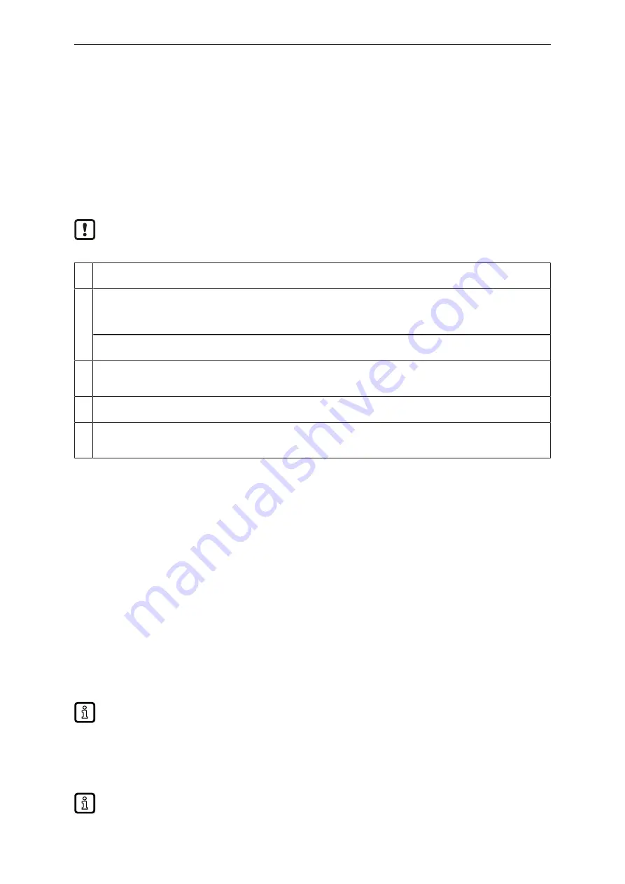
10.1.1 Setting a parameter value

Set the display unit [ Uni ] before the values for the parameters are defined. In case of
subsequent changes of the display unit, rounding errors during internal conversion to other units
may falsify the set values. Selection of the display unit (

Ò


/

 15)

1

Select Parameter

u

Press [MODE/ENTER] until the required parameter is displayed.

2

Set parameter value

u

Press [SET] and keep it pressed.

w

The current parameter value flashes for 5 s.

u

Increase the setting value step by step by pressing the button once or continuously by holding it down.

Decrease the value: let the display move to the maximum setting value. Then the cycle starts again at the minimum set-
ting value.

3

Confirmation of the parameter value

u

Briefly press [MODE/ENTER].

w

The parameter is displayed again; the new parameter value is effective.

4

Set other parameters

u

Start again with step 1.

5

Finish parameter setting

u

Wait for 15 s or press [MODE/ENTER].

w

The current measured value is displayed.

10.1.2 Change from menu level 1 to menu level 2

u

Repeatedly press [MODE/ENTER] until [EF] is displayed.

u

Briefly press [SET].

w

The first parameter of the submenu is displayed.

10.1.3 Electronic lock

The unit can be locked electronically to prevent unauthorised setting. On delivery the unit is not
locked.

Locking

u

Make sure that the unit is in the normal operating mode.

u

Keep [MODE/ENTER] + [SET] pressed until [Loc] is displayed.

w

The unit is locked.

[Loc] is displayed briefly if you try to change parameter values on the locked unit during
operation.

Unlocking

u

Keep [MODE/ENTER] + [SET] pressed until [uLoc] is displayed.

w

The unit is unlocked.

If no button is pressed for 15 s during the setting procedure, the unit returns to the Run mode
with unchanged values.

Summary of Contents for O1D110

Page 1: ...Operating instructions Photoelectric distance sensor O1D110 11418505 00 09 2021 GB...

Page 2: ...10 1 3 Electronic lock 14 10 2 Configuration of the basic settings 15 10 2 1 Selection of the display unit 15 10 2 2 Set the display 15 10 2 3 Configure OUT1 15 10 2 4 Hysteresis function 15 10 2 5 Se...

Page 3: ...Instructions Reaction result Designation of keys buttons or indications Cross reference Important note Non compliance may result in malfunction or interference Information Supplementary note 1 2 Warn...

Page 4: ...he operating instructions or the technical data are not adhered to personal injury and or damage to property may occur The manufacturer assumes no liability or warranty for any consequences caused by...

Page 5: ...Photoelectric distance sensor O1D110 5 Product label...

Page 6: ...a photoelectric distance sensor 3 1 Applications The photoelectric distance sensor measures distances between 0 2 to 10 m It has a background suppression at 10 to 100 m The measured value is shown in...

Page 7: ...nput signal at pin 5 Laser Low not used on High Off 4 5 IO Link IO Link is an internationally standardised IO technology IEC 61131 9 for communicating with sensors and actuators General information ab...

Page 8: ...sured values can be ambiguous 5 2 Mounting accessories The unit is supplied without mounting accessories Examples of mounting accessories Art no Protective cover O1D E21133 Mounting set E2D101 E20938...

Page 9: ...nk master port class A type A For operation with IO Link master port class B type B observe the following As a standard the unit is not compatible with master port class B type B Pin 2 OU2 and pin 5 I...

Page 10: ...hing status Is on if the corresponding output is switched 3 4 digit alphanumeric display Indication of the measured distance the parameters and parameter values 4 Programming button SET Setting of the...

Page 11: ...sis function changes its switching state object near er farther than distance set SP1 is only active if OU1 Hno or Hnc Setting of the switch point for hysteresis function OUT1 16 nSP1 FSP1 Switch poin...

Page 12: ...rate or repeatability Teach mode 19 EF Extended functions Press SET to open the submenu Extended functions Extended functions 20 dS1 dr1 dS2 dr2 Delay for the switching outputs dSx switch on delay dr...

Page 13: ...u Briefly press MODE ENTER w The unit goes to the display mode Internally it remains in the operating mode The set parameter values can be read u To scroll through the parameters briefly press MODE EN...

Page 14: ...lue Then the cycle starts again at the minimum set ting value 3 Confirmation of the parameter value u Briefly press MODE ENTER w The parameter is displayed again the new parameter value is effective 4...

Page 15: ...effect on the outputs OFF the measured value display is deactivated in the Run mode When one button is pressed the current measured value is displayed for 15 s u Confirm with MODE ENTER The LEDs remai...

Page 16: ...off when the object approaches When the object is removed again the output switches Switching state of the outputs Output function Object distance D switching status Hno D SPx Closed D SPx Open Hnc D...

Page 17: ...o Switching state of the outputs Output function Object distance D switching status Fno D nSPx Open D FSPx nSPx D FSPx Closed Fnc D nSPx Closed D FSPx nSPx D FSPx Open Both window limits nSPx and FSPx...

Page 18: ...lect nSP2 and set the switch point near u Confirm with MODE ENTER u Select FSP2 nd set the switch point far u Confirm with MODE ENTER Window function 16 10 2 11 Scaling of the measuring range analogue...

Page 19: ...ctory setting Measuring range scaled MEW Final value of the measuring range In the set measuring range the output signal is between 0 and 10 V 10 3 Teach mode 10 3 1 Setting of the sampling rate The s...

Page 20: ...time for switching outputs u Select EF u Press SET to change to the menu EF u Select parameter with MODE ENTER u dSx switch on delay drx switch off delay u Set the parameter value with SET u Setting r...

Page 21: ...ensor O1D110 21 10 4 4 Display of the software version number u Select EF u Press SET to change to the menu EF u Select SW then press SET w The software version number is displayed u Press MODE ENTER...

Page 22: ...N 3 5 mA 0 V 20 5 mA 10 V NoData OL not enough light no ob ject OFF ON OFF ON 20 5 mA 10 V 3 5 mA 0 V NoData UL nEAr object to be measured outside the measuring range 0 2 m ON OFF OFF ON 3 5 mA 0 V 20...

Page 23: ...sensor free from soiling u For cleaning do not use any solvents or cleaning agents which could damage the plastic parts u After use dispose of the unit in an environmentally friendly way in accordanc...

Reviews: