background image

UK

6

7

5  Electrical connection

The inclination sensor is connected via a 5-pin M12 connector� 

4

2

1

3

5

1: CAN_GND   Ground
2: CAN_V+   supply voltage 24 V DC (+UB)
3: GND        CAN_ supply voltage 0 V DC (+U

B

)

4: CAN_H      High bus cable
5: CAN_L      Low bus cable 

5.1  Bus termination

One terminating resistor is required 


if the sensor is connected at the end or the beginning of the bus�


● in case of a transmission rate ≥ 50 kBaud.

This prevents that information will be transmitted back to the CAN bus�

Dynamic ifm sensors have an integrated (switchable) 120 Ω termination resistor 

that can be activated (1) or deactivated (0)�
The bus wires can be routed in parallel or twisted, with or without shielding in 

accordance with the electromagnetic compatibility requirements� A single line 

structure minimises reflection�
The following diagram shows the components for the physical layer of a two-wire 

CAN bus�

PLC

CANopen

master

 120 Ω 

 120 Ω 

Inclinometer

Inclinometer

other CAN

CAN high wire

CAN low wire

6  Measurement axes

6.1  Dual axis inclination sensor ± 90° (JD23xx)

The X-axis (Roll) and the Y-axis (Pitch) measure the angular position relative to the 

earth vector� Both axes are limited to ± 90°� The sensor is mounted horizontally� 

The X-axis and the Y-axis provide 0° if the inclination sensor is installed in a 

horizontal position�

-X

+X

-Y

+Y

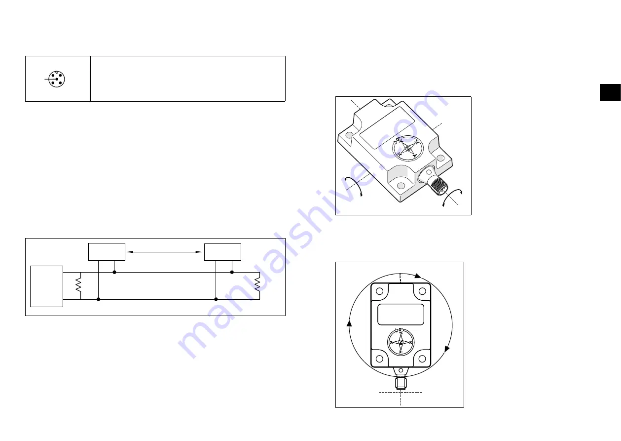
6.2  Single axis inclination sensor 0...360° (JD13xx)

The sensor is mounted vertically� A clockwise rotation around the Z-axis of the 

sensor increases the angle value from 0���360°� When the male connector is 

pointing downwards, the output is 0°�

Z = 0°

Z = 359,9°/

Summary of Contents for JD Series

Page 1: ...Device manual Inclination sensor JD with J1939 interface 80291553 00 05 2020 UK...

Page 2: ...8 8 1 2 PGN 65281 acceleration z gyro x y z 9 8 1 3 PGN 65282 1 axis angle information acceleration x y 9 8 2 PGN 61481 9 8 3 PGN 61481 Slope Sensor Information extended range 10 8 4 Configuration Wr...

Page 3: ...it must be carried out by qualified personnel authorised by the machine operator Protect units and cables against damage 3 Intended use Dynamic MEMS inclination sensors detect and measure the angle of...

Page 4: ...in accordance with the electromagnetic compatibility requirements A single line structure minimises reflection The following diagram shows the components for the physical layer of a two wire CAN bus P...

Page 5: ...90 Acceleration x 32 47 16 1 mg 4000 4000 mg x axis acceleration 4 g range Acceleration y 48 63 16 1 mg 4000 4000 mg y axis acceleration 4 g range 8 1 2 PGN 65281 acceleration z gyro x y z SPN name SP...

Page 6: ...ning Data type 0x0CEF19xx 01 00 xx xx xx xx xx xx Index 0x01 Pitch direction 0 SAE J670 1 opposite direction UINT8 0x0CEF19xx 02 00 xx xx xx xx xx xx Index 0x02 Roll direction 0 SAE J670 1 opposite di...

Page 7: ...s case the sensor transmits the position data after 600 ms but the position data for the following 600 ms is incorrect 8 7 Configuration of read parameters Direction Identifier CAN data Meaning Data t...

Page 8: ...0CEA19xx 00 EF 00 Read request Reply 0x0CEFxx19 12 FF FF FF FF FF FF FF Index 0x12 Serial number default FF FF FF FF UINT32 Enquiry 0x0CEA19xx 00 EF 00 Read request Reply 0x0CEFxx19 13 32 53 4B 41 FF...

Page 9: ...180 180 160 140 120 100 80 60 40 20 11 2 Output Graphs with Preset and Offset JD23xx with a programmed pitch and roll offset of 50 PGN 65280 pitch offset 50 7000000 8000000 9000000 10000000 6000000 5...

Reviews: