background image

RFID-UHF-Antennas 

14

7  Installation / Attachment

To achieve the maximum range with the antenna, there must not be any interfering 

objects between the antenna and the tag to be read� The function of the antenna is 

affected by the type of fixing and the surrounding materials� For optimum antenna 

behaviour there should not be any conducting objects in the vicinity of the antenna� 

The following dimensions are given as adequate distances:
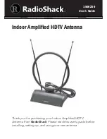
The distance to large metal surfaces and to the ground should be at least 70 cm 

(see Figure 1)�
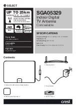
If it is not possible to avoid mounting in front of a metallic surface, a mounting 

support can be used that establishes a distance of exactly 12 cm between the rear 

wall of the antenna and the metal surface (see Figure 2)�
In case of direct mounting on a metallic surface (e� g� a plate as part of a mount-

ing support), the metal plate should be square and have dimensions that do not 

exceed 16 x 16 cm (see Figure 3)�
Other objects such as, e�g�, containers with liquids in the immediate vicinity affect 

the functionality of the antenna�
If these recommended distances cannot be met due to the local situation, the 

antenna characteristics will change such that it will be necessary to re-assess the 

antenna in this special installation situation�

1

2

Minimum spacing on all sides: 70 cm

3

Summary of Contents for Efector 190 ANT820

Page 1: ...Short instructions RFID UHF Antenna Mid Range ANT820 704979 00 01 2012 UK...

Page 2: ...ide range antennas 5 3 4 Antenna type according to read range and transponder shape 6 4 Technical Data 8 5 Reader output power 11 6 Compliance with standards 12 7 Installation Attachment 14 8 Typical...

Page 3: ...fied and trained employees The unit may only be used for the purpose intended by the manufacturer Unauthorized changes to the unit and the use of spare parts and peripheral devices which are not sold...

Page 4: ...ield tags at an extremely limited distance These antennas can also activate loop tags near field tags up to 3 cm The Low range antenna was developed for larger ranges and is particularly suited to nea...

Page 5: ...is used as a characteristic value for circular polariza tion the new model achieves typical values of 1 dB If specified at all the usual value on the market lies at around 3 dB The improved circularit...

Page 6: ...ensures a high read rate and reliable op eration of the system The low range ANT810 ANT910 and ultra low range antennas ANT805 can read loop hybrid and dipole transponders up to 10 cm and offer a very...

Page 7: ...following figure 2m 4m 6m 8m 10m ANT830 70 33 ERP ANT820 100 27 ERP ANT805 ANT810 0 2m 4m 2m 4m Figure Read ranges of the RFID UHF Antennas To achieve the best reading and writing results we recommend...

Page 8: ...r gain is plotted against frequency The operating range of the antenna is shown in grey Outside the operating range the gain of the antenna ANT820 drops off Due to this drop off interference from othe...

Page 9: ...UK RFID UHF Antennas 9 Gain dB Frequency MHz Figure Circular antenna gain against frequency Figure Directional characteristic in azimuth RHC...

Page 10: ...RFID UHF Antennas 10 S Parameters dB Frequenz MHz Figure Matching S11...

Page 11: ...is allowed For other half power beam widths the power is limited to PERP max 0 5 W ERP The ERP is converted in accordance with EN 302 208 1 into output power PC at the reader as follows PC max PERP ma...

Page 12: ...iance with the maximum antenna input power specified in the standard EN 302208 the electrical and magnetic field strength from the antenna ANT820 are below the defined limits at a distance of 20 cm Co...

Page 13: ...tween the different types of exposure Maximum input power ANT805 Distance person antenna 3 cm Distance person antenna 3 cm General public Limit values head and body 2 W kg Pein 340 mW 25 31 dBm Pein 6...

Page 14: ...o avoid mounting in front of a metallic surface a mounting support can be used that establishes a distance of exactly 12 cm between the rear wall of the antenna and the metal surface see Figure 2 In c...

Page 15: ...igure below right away from the antenna and should be laid direct The cable length is to be selected as short as possible to minimise cable losses Cable loops around the antenna or laying the cable in...

Page 16: ...Gate applications for article identification Bulk tag and single tag applications Access systems e g ski lift control systems for travel tickets and admission tickets When using the antennas comply wi...

Page 17: ...in the main radiation di rection for the antenna in question and a reference antenna with the same supply power Reference antennas are isotropic radiators or 2 dipole Frequent logarithmic tasks dBi l...

Page 18: ...2 ERP Effective radiated power Product of the power supplied to a transmitter antenna multiplied by its gain rela tive to a 2 dipole EIRP Equivalent Isotropically Radiated Power Product of the power...

Page 19: ...ed 36 dBm 7 dBi 29 dBm 0 794 W 10 Abbreviations Abbreviations used in this application notes DIN German Institute for Standardisation EIFF Effective Isotropic Field Factor shows the field isolation of...

Reviews: