background image


13 

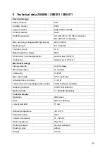
8  Technical data ZB0050 / ZB0051 / ZB0071 

Electrical design


Safety contacts 

4 NC 

Auxiliary contact 

2 NO 

Type of contact 

snap-action contacts   

Contact material 

silver 

Switching capacity 

AC: 240 V/3 A, 120 V/6 A, inductive 
DC: 24 V/2.5 A, inductive 

Max. switching voltage/switching capacity  

240 V/720 VA 

Minimum load 

5 V, 5 mA DC 

Thermal current 

10 A 

Rated Insulation voltage 

500 V 

Short-circuit / overload protection 

external fuse 10A (FF) 

Connection 

terminal up to 2.5 mm 

2


Mechanical design 

Fixing elements  

4 x M5 screws 

Mounting position 

as required 

Cable entry 

4 x M20 

Max. rope length 

125 m each side 

Activation force (on rope) 

< 125 N 

Tension force for operating position (axial) 

130 N (between switches) 

Switching contacts 

to IEC / EN 60947-5-1 

Mechanical life 

> 1,000,000 activations 

Function display 

Operation 

LED green 

Error 

LED red, flashing 

current load LED 

15 mA 


Ambient temperature  

-25...80 °C 

Protection rating 

IP 67 

Vibration resistance 

10 - 500 Hz 

Shock resistance 

15g 11ms 

Housing material 

die-cast aluminium  

Housing colour 

yellow 

Weight 

1320 g 


Summary of Contents for ZB0050

Page 1: ...Operating instructions Safety Rope Emergency Stop Switches ZB0050 ZB0051 ZB0070 ZB0071 ZB0075 7390877 04 05 2019 UK ...

Page 2: ...tion 4 3 Operating and display elements 5 4 Installation 6 5 Function 8 5 1 Maintenance requirement 8 6 Electrical connection 9 7 Safety characteristics 12 8 Technical data ZB0050 ZB0051 ZB0071 13 8 1 Technical data ZB0070 ZB0075 14 9 Scale drawing 15 10 Accessories 15 11 Standards 16 12 Approvals certificates 17 ...

Page 3: ...y any tampering with and or modification to the product will void any manufacturer s liability The unit must be installed connected and put into operation by a qualified electrician trained in safety technology After installation the system must be subjected to a complete function check Disconnect the device externally before handling it Also disconnect any independently supplied relay load circui...

Page 4: ... operation and maintenance Important note The products described here are designed to be components of a safety oriented machine or control system A complete safety related system normally includes sensors evaluation units signalling components and concepts for safe switch off It is the responsibility of each manufacturer of a machine or installation to ensure a correct functioning of the whole sy...

Page 5: ... 3 Operating and display elements 1 red E stop 2 blue reset button 3 dual LED ZB0051 ZB0070 ZB0071 ZB0075 4 rope tension indicator Rope tension indicator Indicator shown with steel rope properly adjusted ...

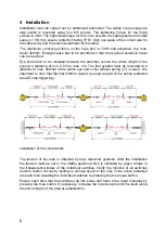
Page 6: ...3m The first eyebolt must be mounted at a distance of max 500mm of the switch eye bolt or the tension spring if it is used It is important to note that the first 500mm cannot be used as part of the active protected area E stop triggering Installation of the components The tension of the rope is obtained by rope tensioner systems After the installation the tension must be set to the middle position...

Page 7: ...ts for rope support Rope pull systems with single direction safety rope emergency stop switches are influenced by fluctuations of the ambient temperature To ensure proper function of the rope pull system it is mandatory to take into account the dependence on the temperature when fixing the rope length and distance of the eye bolts every 3m 25 C 22 C 20 C 15 C 10 C 7 5 C 5 C 3 C Installation Temper...

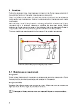
Page 8: ...esetting the E stop signal the cause of the activation has to be determined Reset is only possible with correct rope tension position indication in middle position The max rope length also depends on the change of the ambient temperature Function of the safety rope emergency stop switch 5 1 Maintenance requirement Every week Check proper functioning of the system at various spots along the rope le...

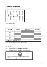
Page 9: ...gement 0 mm 4 0 mm 15 0 mm 17 0 mm 4 NC 2 NO Rope slack Tension range Rope pulled 11 12 21 22 33 34 41 42 51 52 63 64 contact open contact closed Contact travels safety rope emergency stop switch 24 V DC LED 24 V DC on terminal 1 LED display flashing red 24 V DC on terminal 3 LED display permanently green ...

Page 10: ...amming sample Data bits Data bit D3 D2 D1 D0 In Out SI 2 SI 2 SI 1 SI 1 O 1 Activated input channel Bit sequence D3 D0 SI 1 XX00 SI 2 00XX SI 1 and SI 2 0000 keiner XXXX Activated alarm outputs Bit sequence D3 D0 O 1 XXX1 X random ...

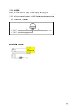
Page 11: ...11 110 V AC LED 110 V AC on terminal 1 red LED display flashing red 110 V AC on terminal 3 green LED display permanently green 0V on terminal 2 black Installation sample ...

Page 12: ... 4 PL e and can be used in applications up to PL e For the PFD PFH values and the MTTFd values of the other components see the respective documentation Explanation of the abbreviations PL Performance Level Capability of safety related parts to perform a safety function at predictable conditions to fulfill the expected risk reduction Cat Category Classification of the safety related parts of a cont...

Page 13: ... fuse 10A FF Connection terminal up to 2 5 mm 2 Mechanical design Fixing elements 4 x M5 screws Mounting position as required Cable entry 4 x M20 Max rope length 125 m each side Activation force on rope 125 N Tension force for operating position axial 130 N between switches Switching contacts to IEC EN 60947 5 1 Mechanical life 1 000 000 activations Function display Operation LED green Error LED r...

Page 14: ...se 10A FF Connection terminal up to 2 5 mm 2 Mechanical design Fixing elements 4 x M5 screws Mounting position as required Cable entry 4 x M20 Max rope length 125 m each side Activation force on rope 125 N Tension force for operating position axial 130 N between switches Switching contacts to IEC EN 60947 5 1 Mechanical life 1 000 000 activations Function display Operation LED green Error LED red ...

Page 15: ...pe tensioner kit stainless steel rope length 5 m ZB0055 Rope tensioner kit stainless steel rope length 10 m ZB0056 Rope tensioner kit stainless steel rope length 20 m ZB0057 Rope tensioner kit stainless steel rope length 50 m ZB0058 Rope tensioner kit stainless steel rope length 80 m ZB0059 Rope tensioner kit stainless steel rope length 100 m ZB0060 Rope tensioner kit stainless steel rope length 1...

Page 16: ... 3 20 0 52 5 18 0 82 7 16 1 3 10 Hints for AS4024 3610 3614 Information with regard to AS4024 2014 1 Perpendicular force to operate the switches midway between eyebolt Supports Check 70N rope deflection 300mm 2 Axial force direct along rope axis 230N Typical 125N Typical parameters for successful operation of a system is less than 70N pulling force with less than 150mm deflection of rope between e...

Page 17: ...17 12 Approvals certificates EC declaration of conformity TÜV Rheinland pending UL cULus AS NSZ 4024 1 ...

Page 18: ...E 15125 Amaroussio Tel 30 210 6180090 H ifm electronic kft 9028 Györ Tel 36 96 518 397 I ifm electronic s a 20041 Agrate Brianza MI Tel 39 039 68 99 982 IL Astragal Ltd Azur 58001 Tel 972 3 559 1660 IND ifm electronic India Branch Office Kolhapur 416234 Tel 91 231 267 27 70 J efector co ltd Chiba shi Chiba 261 7118 Tel 81 043 299 2070 MAL ifm electronic Pte Ltd 47100 Puchong Selangor Tel 603 8063 ...

Reviews: