background image

FDT Tools

FDT-Specification Basics 

ifak system GmbH

3

C

H A P T E R

  2 :

FDT – A B

RIEF

 I

NTRODUCTION

FDT-Specification Basics

The widespread technologies COM (Common Object Model), 
XML (eXtensible Mark-up Language) and ActiveX (a COM 
based technology for GUI elements) form the basis platform of 
FDT. 

COM integrates the different software components and facilitates 
the interaction between them. Another example for the use of 
COM as underlying concept of an automation standard can be 
found in the area of online data exchange. There, the specifica-
tion OPC (DA) defines the interfaces and mechanisms for the 
interaction between independent software components employ-
ing COM functionality.

Compared to OPC the aims of FDT are quite more challenging. 
The COM functions transfer XML documents, which contain the 
data to be communicated between different components. The 
data which may be of different levels of complexity convey 
information about the various aspects of the software component 
(general information like manufacturer and device type; sup-
ported functions, communication data).

The ActiveX technology was chosen in order to integrate device 
specific dialog elements in the HMI of the engineering system. 
FDT adds new functions to the already existing ActiveX function 
set, to adapt the standard to the special needs of FDT. For a 
seamless integration of all components FDT specifies (with more 
or less depth) the object model, interfaces and XML schemas, as 
well as a session and data management.

Summary of Contents for is Pro DP/PA Link DTM

Page 1: ...TECHNOLOGIEN MIT VORSPRUNG is Pro DP PA Link DTM User Manual...

Page 2: ...ng taping or storage in an information retrieval system without prior written permission of the ifak system GmbH Information in this manual is subject to change without notice and does not represent a...

Page 3: ...ntroduction FDT Specification Basics 3 Object Model 4 Component interaction 7 Summary Objects in the FDT concept 9 DeviceDTM 9 ActiveX 9 CommDTM 9 CommChannel 10 Chapter 3 Gateway DTM is Pro DP PA Lin...

Page 4: ...is Pro DP PA Link DTM II ifak system GmbH...

Page 5: ...PCI of ifak system or with a communication interface and FDT software of any manufacturer Software Installation The operation of the GatewayDTM requires the correct installa tion of a Profibus Master...

Page 6: ...out the manual different fonts are used to indicate differ ent meanings Our Service In case you have any questions concerning the is Pro DP PA Link DTM which can t be solved by this manual please cont...

Page 7: ...ents employ ing COM functionality Compared to OPC the aims of FDT are quite more challenging The COM functions transfer XML documents which contain the data to be communicated between different compon...

Page 8: ...erver handles the tasks of management and configuration of a device class as defined by the manufac turer This device class might be one device type or a group of devices A typical DTM contains no gra...

Page 9: ...tem one Device DTM must exist for every device The DeviceDTM will be provided by the device manufacturer A DTM for a device class with direct access to a communication device e g a Profibus interface...

Page 10: ...rough a CommChannel and the underlying fieldbus interface Lets draw a comparison between the FDT terms DeviceDTM CommDTM CommChannel and the terms in use within the domain of automation software A Dev...

Page 11: ...ies The DTM itself accesses the frame through another set of interfaces which allow the DTM to acquire information from and transmit data to the frame Component interaction Before going into more deta...

Page 12: ...ished To achieve this the channel supports the interface IFdtCommunication The interface contains the fieldbus access functionality connection establishment termination data trans fer The communicatio...

Page 13: ...om the DTM ActiveX The ActiveX are the visible components of a FDT application as far as device functionality is concerned DTM and channel objects provide interfaces for the configuration diagnosis do...

Page 14: ...re sent received and manged by the CommChannel A pointer to the main interface of the channel IFdtCommunication is passed to the DeviceDTM The channel provides the interface IFdtChannelSubTopology whi...

Page 15: ...eway DTM can be inte grated into any frame application e g Pactware First one has to install the software see chapter 1 Start your frame application Then the device catalog has to be updated Now the i...

Page 16: ...se otherwise existing connections could be disconnected Figure 5 Change of DeviceDTM Addresses The list on the left side shows connected DeviceDTMs The but ton Refresh List updates the list with the c...

Page 17: ...lows a ScanRequest only for the DTM states ONLINE COMMUNICATIONSET and GOINGONLINE The Gate way DTM follows the specification and allows only querying for devices on the bus when the Gateway DTM is co...

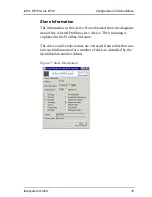
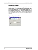
Page 18: ...X with additional information about a device can be opened by selecting the button Extended Information for a chosen slave device The button Change Address opens another ActiveX for changing the addre...

Page 19: ...iveX are obtained from the diagnosis data of the selected Profibus slave device Their meaning is explained in the Profibus literature The device and vendor names are extracted from tables that con tai...

Page 20: ...bus slave device The current address is set automatically when the ActiveX is opened The new address is not allowed to be in use at the same Profibus segment The DTM checks the existence of the targe...

Reviews: