PNG3XX INSTALLATION MANUAL
NAM-PNG3xx-TM-EN-C.doc
The info rmation contained in this d ocu ment is the p roperty of Auto matic
Syste ms and is co nfidentia l. The re cipient shall refrain fro m using it fo r a ny
purpose other than the use of the pro ducts or the execu tion of the pro ject to
which it refers and fro m co mmunicating it to third partie s without written p rio r
agree ment of Auto matic Syste ms. Do cu ment sub ject to change without notice.
35
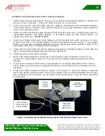
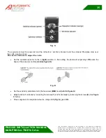
Fig. A
The equipment must be powered and the reflectors / emitter photocell and the smoked Plexiglas strip over
the cells must be clean.
Proceed as follows to adjust the cells:
•
Set the operation selector to the L
(light)
position. In this setting, the photocell output stays
ON
when the
beam of the sensor is not blocked
(See figure B)
:
Fig. B
•
Set the sensitivity potentiometer to the maximum
(MAX)
level
(refer to figure A)
.
•
Adjust each cell vertically by loosening the screws
(1)
and horizontally by loosening the screws
(2)
. See
figure
C
below.
•
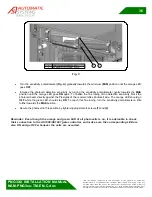
Proper alignment is completed when the orange LED
(Fig. A)
goes
ON
.

