PNG3XX INSTALLATION MANUAL
NAM-PNG3xx-TM-EN-C.doc
The info rmation contained in this d ocu ment is the p roperty of Auto matic
Syste ms and is co nfidentia l. The re cipient shall refrain fro m using it fo r a ny
purpose other than the use of the pro ducts or the execu tion of the pro ject to
which it refers and fro m co mmunicating it to third partie s without written p rio r
agree ment of Auto matic Syste ms. Do cu ment sub ject to change without notice.
34
3. START-UP
3.1 Final Adjustments
Photocell
locations and quantities are shown in the figure below. Please note the different quantities
according to model number.
Figure 28: Cell Numbers
3.1.1 Detailed Calibration Method of Omron Type Photocells
The proper operation of the PNG gate requires the correct alignment of the photocells: the infrared beam
must be as best as possible centered on the corresponding reflector/receiving photocell. Moreover, their
sensitivity must be correctly adjusted, so as to ensure an optimal detection level.
The lens of the cell must be kept clean. All optical systems being influenced by the environment in which
they are situated, the presence of haze, mist, smoke, fumes, dust, etc. may affect their operation by
reducing the sensing distance. Use domestic type of window cleaner (“Windex”) when cleaning the lens.
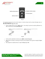
Each photocell comprises 2 potentiometers and 2 LED, a green and an orange
(see figure A)
. Green LED
shows the photocell stability, orange LED shows the photocell output level
(ON/OFF)
. Sensitivity
potentiometer will set photocell detection level; operation selector will set the output level of the photocell.
PNG381-391
PNG380-390
PNG382-392


