PNG3XX INSTALLATION MANUAL
NAM-PNG3xx-TM-EN-C.doc
The info rmation contained in this d ocu ment is the p roperty of Auto matic
Syste ms and is co nfidentia l. The re cipient shall refrain fro m using it fo r a ny
purpose other than the use of the pro ducts or the execu tion of the pro ject to
which it refers and fro m co mmunicating it to third partie s without written p rio r
agree ment of Auto matic Syste ms. Do cu ment sub ject to change without notice.
17
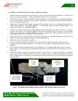
2.2.3 Location MR (Master Rear):
The Figure 12
represents the Master unit (right) and Intermediate unit Master Side PLC backplate.
However note that the motor under the interface board (AS1007) and the low voltage terminal blocks are
present only in an intermediate unit.
Figure 12: PLC Backplate and Main Power Supply Junction Box
Programmable
Logic Controller
PLC
Interface Board
AS-1007
120 V AC
Incoming
Power Supply
Junction Box
Low voltage
interconnect terminal
blocks
(Only in Intermediate)
Motor
(Only in intermediate)


