


PPC-51xxA-H61 Panel PC
Page 54
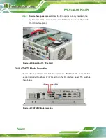
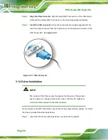
Figure 3-34: LAN Connection
Step 3:
Insert the LAN cable RJ-45 connector
. Once aligned, gently insert the LAN
cable RJ-45 connector into the on-board RJ-45 connector.
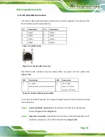
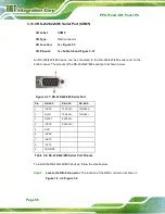
3.13.3 RS-232 Serial Ports (COM1, COM2, COM3, COM4)
CN Label:
COM1, COM2, COM3, COM4
CN Type:
DB-9 connector
CN Location:
See
6
Figure 1-5
and
Figure 1-6
CN Pinouts:
See
Table 3-7 and Figure 3-35
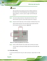
An RS-232 device can be connected to the RS-232 serial port on the bottom panel. The
pinouts of the RS-232 serial port is shown below.
Figure 3-35: RS-232 Serial Port
Summary of Contents for PPC-51 A-H61 Series
Page 11: ...PPC 51xxA H61 Panel PC Page xi Figure 6 2 Main Board Layout Diagram Solder Side 106 ...
Page 14: ...PPC 51xxA H61 Panel PC Page 1 1 Introduction Chapter 1 ...
Page 20: ...PPC 51xxA H61 Panel PC Page 7 Figure 1 5 PPC 5150A H61 PPC 5170A H61 Bottom View ...
Page 30: ...PPC 51xxA H61 Panel PC Page 17 2 Unpacking Chapter 2 ...
Page 35: ...PPC 51xxA H61 Panel PC Page 22 3 Installation Chapter 3 ...
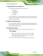
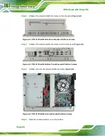
Page 49: ...PPC 51xxA H61 Panel PC Page 36 Figure 3 14 Replacing the Optical Drive Bracket ...
Page 75: ...PPC 51xxA H61 Panel PC Page 62 Chapter 4 4 System Maintenance ...
Page 84: ...PPC 51xxA H61 Panel PC Page 71 5 BIOS Setup Chapter 5 ...
Page 117: ...PPC 51xxA H61 Panel PC Page 104 6 Interface Connectors Chapter 6 ...
Page 136: ...PPC 51xxA H61 Panel PC Page 123 Appendix A A Regulatory Compliance ...
Page 141: ...PPC 51xxA H61 Panel PC Page 128 B BIOS Configuration Options Appendix B ...
Page 144: ...PPC 51xxA H61 Panel PC Page 131 C Safety Precautions Appendix C ...
Page 149: ...PPC 51xxA H61 Panel PC Page 136 D Watchdog Timer Appendix D ...
Page 152: ...PPC 51xxA H61 Panel PC Page 139 E Hazardous Materials Disclosure Appendix E ...


