


PPC-51xxA-H61 Panel PC
Page 106
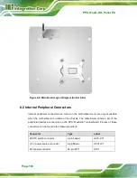
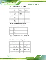
Figure 6-2: Main Board Layout Diagram (Solder Side)
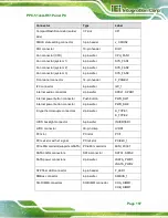
6.2 Internal Peripheral Connectors
Internal peripheral connectors are found on the motherboard and are only accessible
when the motherboard is outside of the chassis. The table below shows a list of the
peripheral interface connectors on the PPC-51xxA-H61 motherboard. Pinouts of these
connectors can be found in the following sections.
Connector
Type
Label
AT/ATX switch connector
2-pin header
JATX_AT1
+12V power source connector
4-pin Molex
CPU12V1
ATX power connector
24-pin ATX
ATX1
Summary of Contents for PPC-51 A-H61 Series
Page 11: ...PPC 51xxA H61 Panel PC Page xi Figure 6 2 Main Board Layout Diagram Solder Side 106 ...
Page 14: ...PPC 51xxA H61 Panel PC Page 1 1 Introduction Chapter 1 ...
Page 20: ...PPC 51xxA H61 Panel PC Page 7 Figure 1 5 PPC 5150A H61 PPC 5170A H61 Bottom View ...
Page 30: ...PPC 51xxA H61 Panel PC Page 17 2 Unpacking Chapter 2 ...
Page 35: ...PPC 51xxA H61 Panel PC Page 22 3 Installation Chapter 3 ...
Page 49: ...PPC 51xxA H61 Panel PC Page 36 Figure 3 14 Replacing the Optical Drive Bracket ...
Page 75: ...PPC 51xxA H61 Panel PC Page 62 Chapter 4 4 System Maintenance ...
Page 84: ...PPC 51xxA H61 Panel PC Page 71 5 BIOS Setup Chapter 5 ...
Page 117: ...PPC 51xxA H61 Panel PC Page 104 6 Interface Connectors Chapter 6 ...
Page 136: ...PPC 51xxA H61 Panel PC Page 123 Appendix A A Regulatory Compliance ...
Page 141: ...PPC 51xxA H61 Panel PC Page 128 B BIOS Configuration Options Appendix B ...
Page 144: ...PPC 51xxA H61 Panel PC Page 131 C Safety Precautions Appendix C ...
Page 149: ...PPC 51xxA H61 Panel PC Page 136 D Watchdog Timer Appendix D ...
Page 152: ...PPC 51xxA H61 Panel PC Page 139 E Hazardous Materials Disclosure Appendix E ...


