


PM-PV-D4251/N4551/D5251 User Manual
Page 54
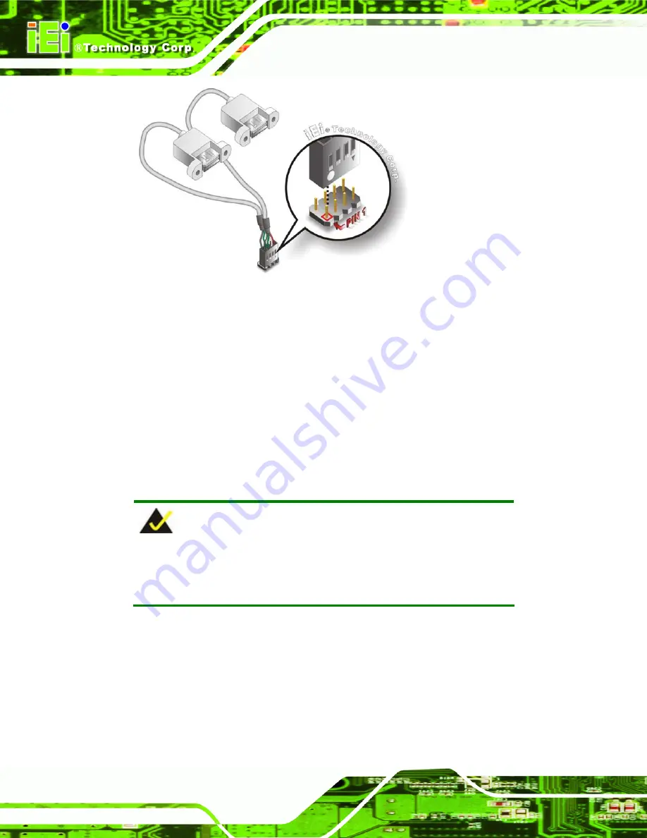
Figure 4-14: Dual USB Cable Connection
Step 4:
Attach the USB connectors to the chassis
. The USB 2.0 connectors each of
two retention screw holes. To secure the connectors to the chassis please refer
to the installation instructions that came with the chassis.
Step 0:
4.9 Software Installation
All the drivers for the PM-PV-D4251/N4551/D5251 are on the CD that came with the
system. To install the drivers, please follow the steps below.
Step 1:
Insert the CD into a CD drive connected to the system.
NOTE:
If the installation program doesn't start automatically:
Click "Start->My Computer->CD Drive->autorun.exe"
Step 2:
The driver main menu appears (
).
Summary of Contents for PM-PV-D4251
Page 13: ...PM PV D4251 N4551 D5251 User Manual Page 1 Chapter 1 1 Introduction ...
Page 19: ...PM PV D4251 N4551 D5251 User Manual Page 7 Figure 1 6 Dimensions Bottom ...
Page 23: ...PM PV D4251 N4551 D5251 User Manual Page 11 Chapter 2 2 Unpacking ...
Page 27: ...PM PV D4251 N4551 D5251 User Manual Page 15 Chapter 3 3 Connectors ...
Page 47: ...PM PV D4251 N4551 D5251 User Manual Page 35 Chapter 4 4 Installation ...
Page 69: ...PM PV D4251 N4551 D5251 User Manual Page 57 Chapter 5 5 BIOS ...
Page 97: ...PM PV D4251 N4551 D5251 User Manual Page 85 Appendix A A BIOS Options ...
Page 100: ...PM PV D4251 N4551 D5251 User Manual Page 88 Appendix B B One Key Recovery ...
Page 128: ...PM PV D4251 N4551 D5251 User Manual Page 116 Appendix C C Terminology ...
Page 132: ...PM PV D4251 N4551 D5251 User Manual Page 120 Appendix D D Digital I O Interface ...
Page 135: ...PM PV D4251 N4551 D5251 User Manual Page 123 Appendix E E Watchdog Timer ...
Page 138: ...PM PV D4251 N4551 D5251 User Manual Page 126 Appendix F F Hazardous Materials Disclosure ...


