PCIE-9152 PCIMG 1.3 CPU Card
Page 82
5.7.2 USB Device Connection (Single Connector)
There are two external USB 2.0 connectors. Both connectors are perpendicular to the
PCIE-9152. To connect a USB 2.0 or USB 1.1 device, please follow the instructions
below.
Step 1:
Located the USB connectors
. The locations of the USB connectors are shown
in
Chapter 4
.
Step 2:
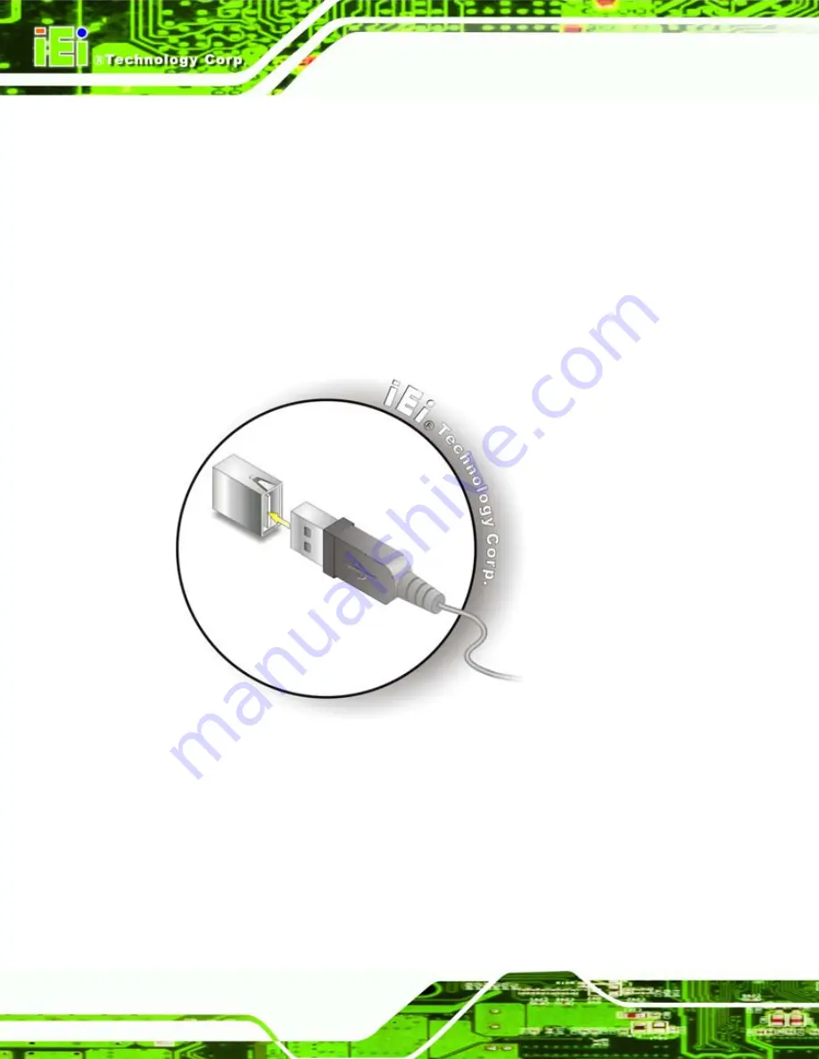
Align the connectors.
Align the USB device connector with one of the
connectors on the PCIE-9152. See
Figure 5-23: USB Device Connection
Step 3:
Insert the device connector.
Once aligned, gently insert the USB device
connector into the onboard connector.
Step 0:
Summary of Contents for PCIE-9152
Page 17: ...PCIE 9152 PCIMG 1 3 CPU Card Page 1 Chapter 1 1 Introduction...
Page 22: ...PCIE 9152 PCIMG 1 3 CPU Card Page 6 Chapter 2 2 Detailed Specifications...
Page 38: ...PCIE 9152 PCIMG 1 3 CPU Card Page 22 Chapter 3 3 Unpacking...
Page 43: ...PCIE 9152 PCIMG 1 3 CPU Card Page 27 Chapter 4 4 Connector Pinouts...
Page 67: ...PCIE 9152 PCIMG 1 3 CPU Card Page 51 Chapter 5 5 Installation...
Page 100: ...PCIE 9152 PCIMG 1 3 CPU Card Page 84 Chapter 6 6 BIOS...
Page 105: ...PCIE 9152 PCIMG 1 3 CPU Card Page 89 BIOS Menu 2 Advanced...
Page 146: ...PCIE 9152 PCIMG 1 3 CPU Card Page 130 Chapter 7 7 Software Installation...
Page 166: ...PCIE 9152 PCIMG 1 3 CPU Card Page 150 Appendix A A BIOS Options...
Page 169: ...PCIE 9152 PCIMG 1 3 CPU Card Page 153...
Page 170: ...PCIE 9152 PCIMG 1 3 CPU Card Page 154 Appendix B B Terminology...
Page 174: ...PCIE 9152 PCIMG 1 3 CPU Card Page 158 Appendix C C Digital I O Interface...
Page 177: ...PCIE 9152 PCIMG 1 3 CPU Card Page 161 Appendix D D Watchdog Timer...
Page 180: ...PCIE 9152 PCIMG 1 3 CPU Card Page 164 Appendix E E Address Mapping...
Page 182: ...PCIE 9152 PCIMG 1 3 CPU Card Page 166 Figure E 3 Input Output IO 2 of 2...
Page 184: ...PCIE 9152 PCIMG 1 3 CPU Card Page 168 E 4 Memory Figure E 5 Memory...
Page 185: ...PCIE 9152 PCIMG 1 3 CPU Card Page 169 Appendix F F Hazardous Materials Disclosure...


