


KINO-AA750-i2 Mini-ITX SBC
Page 59
Step 3:
Correctly Orientate the CPU
. Make sure the pins are facing down.
Step 4:
Correctly position the CPU
. Match the Pin 1 mark on the CPU with the marked
corner on the CPU socket. See
Figure 4-1
.
Step 5:
Align the CPU pins
. Carefully align the CPU pins with the holes in the CPU
socket.
Step 6:
Insert the CPU
. Gently insert the CPU into the socket. If lined up correctly, the
CPU will gently drop into the correct position.
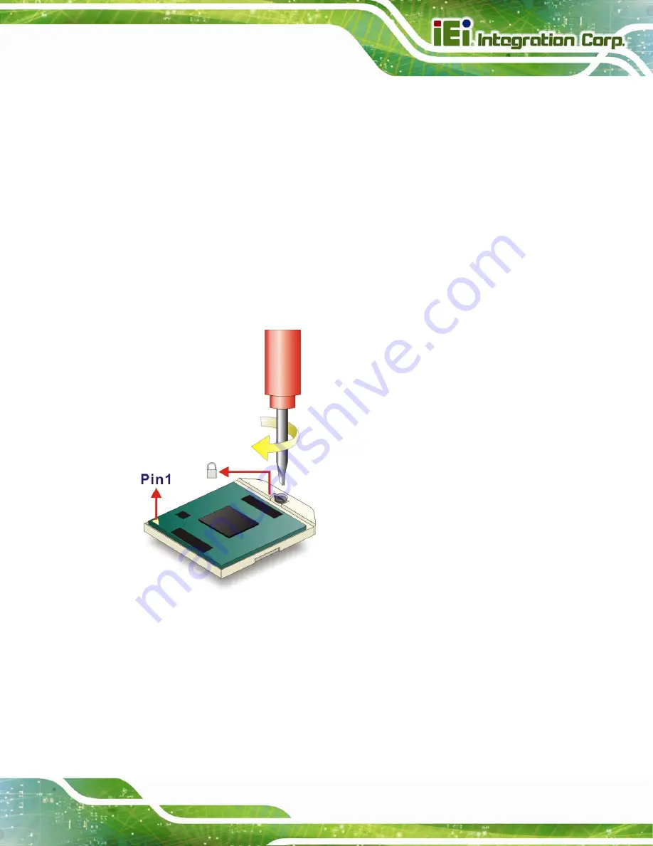
Step 7:
Lock the retention screw
. Rotate the retention screw into the locked position.
See
Figure 4-2
.
Step 0:
Figure 4-2: Lock the CPU Socket Retention Screw
Summary of Contents for KINO-AA750-i2
Page 16: ...KINO AA750 i2 Mini ITX SBC Page 1 Chapter 1 1 Introduction...
Page 20: ...KINO AA750 i2 Mini ITX SBC Page 5 Figure 1 3 Connectors Solder Side...
Page 26: ...KINO AA750 i2 Mini ITX SBC Page 11 Chapter 2 2 Packing List...
Page 31: ...KINO AA750 i2 Mini ITX SBC Page 16 Chapter 3 3 Connectors...
Page 70: ...KINO AA750 i2 Mini ITX SBC Page 55 Chapter 4 4 Installation...
Page 98: ...KINO AA750 i2 Mini ITX SBC Page 83 Chapter 5 5 BIOS...
Page 127: ...KINO AA750 i2 Mini ITX SBC Page 112 6 Software Drivers Chapter 6...
Page 138: ...KINO AA750 i2 Mini ITX SBC Page 123 Appendix A A BIOS Options...
Page 141: ...KINO AA750 i2 Mini ITX SBC Page 126 Appendix B B One Key Recovery...
Page 149: ...KINO AA750 i2 Mini ITX SBC Page 134 Figure B 5 Partition Creation Commands...
Page 183: ...KINO AA750 i2 Mini ITX SBC Page 168 Appendix C C Terminology...
Page 187: ...KINO AA750 i2 Mini ITX SBC Page 172 Appendix D D Digital I O Interface...
Page 190: ...KINO AA750 i2 Mini ITX SBC Page 175 Appendix E E Hazardous Materials Disclosure...


