


ITG-100-AL Embedded System
Page 29
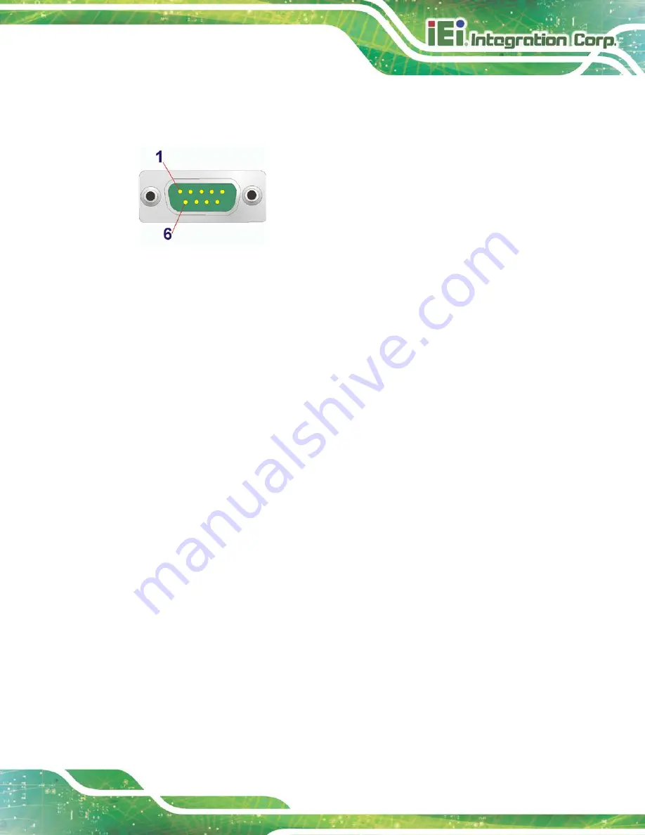
Step 3:
Secure the connector
. Secure the serial device connector to the external
interface by tightening the two retention screws on either side of the connector.
Figure 3-21: DB-9 RS-232/422/485 Serial Port Connector
3.11.2 RJ-45 RS-232/422/485 Serial Port Connection
The RJ-45 RS-232/422/485 serial port connects to a cable with a standard DB-9
connector at the other end (cables included). Follow the steps below to connect a serial
device to the ITG-100-AL.
Step 1:
Locate the RJ-45 connector
. The location of the RJ-45 serial port connector is
shown in
Chapter 2
. The RJ-45 connectors for the serial ports can be identified
easily as the RJ-45 for the network has two LEDs on the port, while the
connectors for the serial cables don’t.
Step 2:
Insert the RJ-45 to DB-9 cable.
Step 3:
Insert the serial connector
.
Insert the DB-9 connector of a serial device into
the DB-9 connector on the cable. See
Summary of Contents for ITG-100-AL
Page 14: ...ITG 100 AL Embedded System Page 2 Chapter 1 1 Introduction ...
Page 19: ...ITG 100 AL Embedded System Page 7 Figure 1 3 ITG 100 AL Front Panel ...
Page 22: ...ITG 100 AL Embedded System Page 10 Chapter 2 2 Unpacking ...
Page 25: ...ITG 100 AL Embedded System Page 13 Chapter 3 3 Installation ...
Page 44: ...ITG 100 AL Embedded System Page 32 4 System Motherboard Chapter 4 ...
Page 54: ...ITG 100 AL Embedded System Page 42 Chapter 5 5 BIOS ...
Page 83: ...ITG 100 AL Embedded System Page 71 Chapter 6 6 Software Installation ...
Page 86: ...ITG 100 AL Embedded System Page 74 Appendix A A Regulatory Compliance ...
Page 92: ...ITG 100 AL Embedded System Page 80 B Safety Precautions Appendix B ...
Page 98: ...ITG 100 AL Embedded System Page 86 Appendix C C BIOS Menu Options ...
Page 101: ...ITG 100 AL Embedded System Page 89 Appendix D D Terminology ...
Page 105: ...ITG 100 AL Embedded System Page 93 Appendix E E Hazardous Materials Disclosure ...


