IDS-310-AL Embedded System
Page 21
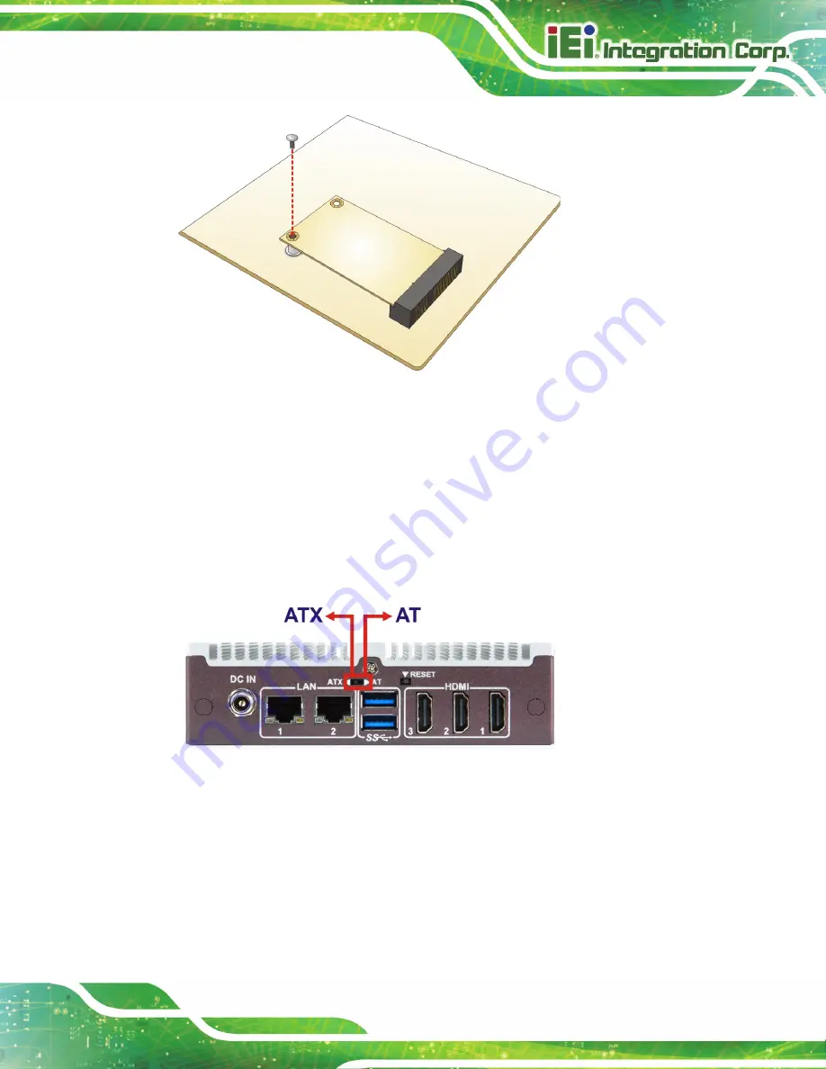
Figure 3-13: Securing the PCIe Mini Module
Step 6:
Attach the RTC battery onto the PCIe Mini module.
Step 0:
3.6 AT/ATX Power Mode Selection
AT and ATX power modes can both be used on the IDS-310-AL series. The selection is
made through an AT/ATX switch on the rear panel (
).
Figure 3-14: AT/ATX Switch Location
Summary of Contents for IDS-310-AL
Page 15: ...IDS 310 AL Embedded System Page 1 Chapter 1 1 Introduction...
Page 23: ...IDS 310 AL Embedded System Page 9 Chapter 2 2 Unpacking...
Page 26: ...IDS 310 AL Embedded System Page 12 Chapter 3 3 Installation...
Page 37: ...IDS 310 AL Embedded System Page 23 Figure 3 16 Hook Onto Mounting Bracket...
Page 47: ...IDS 310 AL Embedded System Page 33 Chapter 4 4 BIOS...
Page 81: ...IDS 310 AL Embedded System Page 67 Chapter 5 5 Maintenance...
Page 85: ...IDS 310 AL Embedded System Page 71 Chapter 6 6 Interface Connectors...
Page 93: ...IDS 310 AL Embedded System Page 79 Appendix A A Regulatory Compliance...
Page 98: ...IDS 310 AL Embedded System Page 84 Appendix B B Safety Precautions...
Page 104: ...IDS 310 AL Embedded System Page 90 Appendix C C BIOS Menu Options...
Page 107: ...IDS 310 AL Embedded System Page 93 Appendix D D Watchdog Timer...
Page 110: ...IDS 310 AL Embedded System Page 96 Appendix E E Error Beep Code...
Page 112: ...IDS 310 AL Embedded System Page 98 Appendix F F Hazardous Materials Disclosure...


