AFL4-W07-EHL Panel PC
Page 54
5.3.1
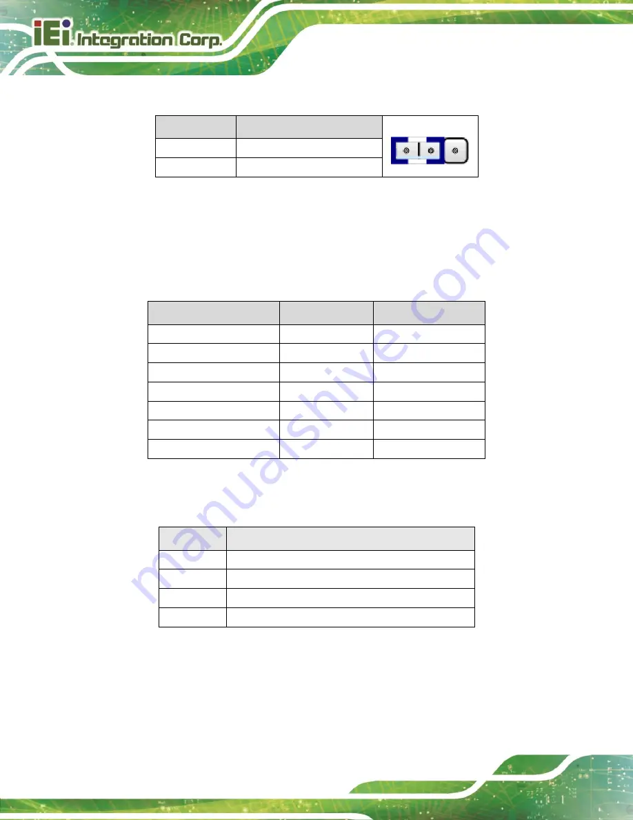
Flash Descriptor Security Override
J_FLASH1
DESCRIPTION
1-2(default)*
LOW = Disabled (No override)
Short 2-3
High = Enabled (OVERIDE)
Table 5-16: J_FLASH1 Connector
5.4
External Interface Panel Connectors
The table below lists the rear panel connectors on the AFL4-W07-EHL motherboard.
Pinouts of these connectors can be found in the following sections.
Connector
Type
Label
USB 2.0 Connectors
USB 2.0 port
USB_CON1
USB 3.2 Gen 2 Connectors
USB 3.2 Gen 2 port
USB_CON2/ USB_CON3
DC Input Connector
DC jack
PWR1
Power Button
Push button
PWR_SW1
RS-232/422/485 Serial ports
DB-9
COM1/COM2
2.5GbE LAN Connector
RJ45
J_LAN1
HDMI Connector
HDMI
HDMI1
Table 5-17: Rear Panel Connectors
5.4.1
USB 2.0 Connector (USB_CON1)
PIN NO.
DESCRIPTION
1
VCC
2
USB_PN-
3
4
GND
Table 5-18: USB 2.0 Connector (USB_CON1) Pinouts
Summary of Contents for AFL4-W07-EHL
Page 3: ...AFL4 W07 EHL Panel PC Page ii Revision Date Version Changes April 6 2023 1 00 Initial release...
Page 13: ...AFL4 W07 EHL Panel PC Page 12 1 Introduction Chapter 1...
Page 20: ...AFL4 W07 EHL Panel PC Page 19 2 Unpacking Chapter 2...
Page 24: ...AFL4 W07 EHL Panel PC Page 23 3 Installation Chapter 3...
Page 41: ...AFL4 W07 EHL Panel PC Page 40 4 System Maintenance Chapter 4...
Page 46: ...AFL4 W07 EHL Panel PC Page 45 5 Interface Connectors Chapter 5...
Page 59: ...AFL4 W07 EHL Panel PC Page 58 Appendix A A Regulatory Compliance...
Page 65: ...AFL4 W07 EHL Panel PC Page 64 B Safety Precautions Appendix B...
Page 71: ...AFL4 W07 EHL Panel PC Page 70 C Watchdog Timer Appendix C...
Page 74: ...AFL4 W07 EHL Panel PC Page 73 Appendix D D Hazardous Materials Disclosure...


