AFL2-W15A-N270/L325 Panel PC
Page 17
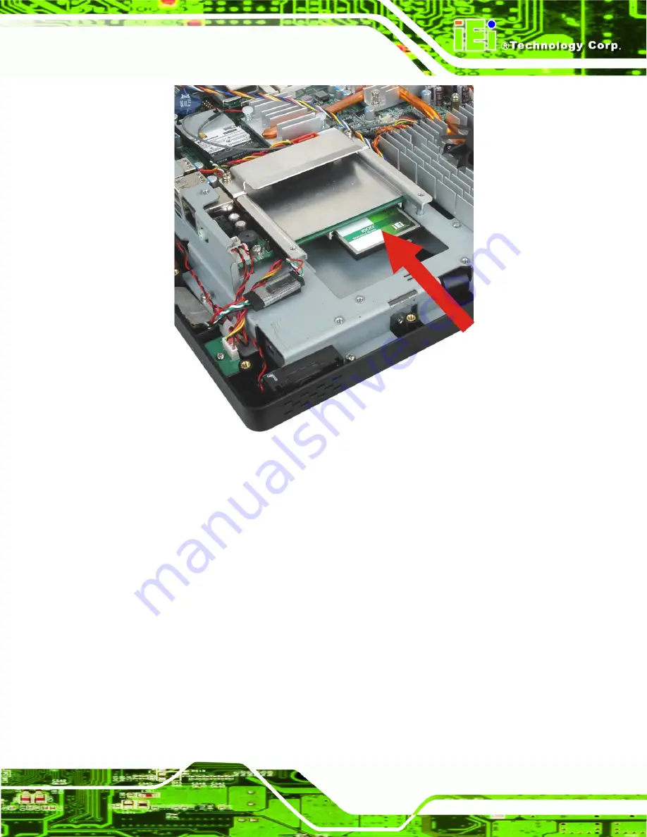
Figure 2–5: CompactFlash® Install (shown with all covers removed)
Step 4:
Replace the brackets, access panel and screws.
S
te
p
0
:
2.5 Expansion Module Installation
This section outlines the installation of the expansion modules in the
AFL2-W15A-N270/L325. To install the modules, please follow the steps below:
Step 1:
Unfasten the left plastic side access panel (Expansion module access panel)
retention screws and remove the left plastic side access panel (
See figure
below
).
Summary of Contents for AFL2-W15A-N270/L325
Page 13: ...AFL2 W15A N270 L325 Panel PC Page 1 Chapter 1 1 Introduction...
Page 22: ...AFL2 W15A N270 L325 Panel PC Page 10 Chapter 2 2 Installation...
Page 64: ...AFL2 W15A N270 L325 Panel PC Page 52 Chapter 3 3 BIOS Setup...
Page 109: ...AFL2 W15A N270 L325 Panel PC Page 97 Chapter 4 4 System Maintenance...
Page 113: ...AFL2 W15A N270 L325 Panel PC Page 101 Appendix A A Safety Precautions...
Page 118: ...AFL2 W15A N270 L325 Panel PC Page 106 Appendix B B One Key Recovery...
Page 146: ...AFL2 W15A N270 L325 Panel PC Page 134 Appendix C C BIOS Options...
Page 150: ...AFL2 W15A N270 L325 Panel PC Page 138 Appendix D D Expansion Module Dimensions...
Page 153: ...AFL2 W15A N270 L325 Panel PC Page 141 Appendix E E Terminology...
Page 157: ...AFL2 W15A N270 L325 Panel PC Page 145 Appendix F F Watchdog Timer...
Page 160: ...AFL2 W15A N270 L325 Panel PC Page 148 Appendix G G Hazardous Materials Disclosure...
Page 164: ...AFL2 W15A N270 L325 Panel PC Page 152 Appendix H H International Standards Compliance...


