AFL2-12A-HM65 Series Panel PC
Page 41
Step 7:
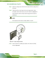
Align the mounting screws on the monitor rear panel with the mounting holes on
the bracket.
Step 8:
Carefully insert the screws through the holes and gently pull the monitor
downwards until the monitor rests securely in the slotted holes (
6
Figure 4-17
).
Ensure that all four of the mounting screws fit snuggly into their respective
slotted holes.
NOTE:
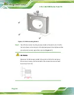
In the diagram below the bracket is already installed on the wall.
Figure 4-17: Chassis Support Screws
Step 9:
Secure the panel PC by fastening the captive screw of the wall-mounting
bracket. (
6
Figure 4-18
).
Summary of Contents for AFL2-12A-HM65/PC-EM-R11
Page 15: ...AFL2 12A HM65 Series Panel PC Page 1 1 Introduction Chapter 1...
Page 26: ...AFL2 12A HM65 Series Panel PC Page 12 2 Detailed Specifications Chapter 2...
Page 33: ...AFL2 12A HM65 Series Panel PC Page 19 3 Unpacking Chapter 3...
Page 38: ...AFL2 12A HM65 Series Panel PC Page 24 4 Installation Chapter 4...
Page 64: ...AFL2 12A HM65 Series Panel PC Page 50 5 System Maintenance Chapter 5...
Page 73: ...AFL2 12A HM65 Series Panel PC Page 59 6 AMI BIOS Setup Chapter 6...
Page 108: ...AFL2 12A HM65 Series Panel PC Page 94 7 Software Drivers Chapter 7...
Page 130: ...AFL2 12A HM65 Series Panel PC Page 116 Appendix A A Interface Connectors...
Page 137: ...AFL2 12A HM65 Series Panel PC Page 123 B Safety Precautions Appendix B...
Page 142: ...AFL2 12A HM65 Series Panel PC Page 128 C BIOS Configuration Options Appendix C...
Page 145: ...AFL2 12A HM65 Series Panel PC Page 131 Appendix D D One Key Recovery...
Page 153: ...AFL2 12A HM65 Series Panel PC Page 139 Figure D 5 Partition Creation Commands...
Page 187: ...AFL2 12A HM65 Series Panel PC Page 173 E Watchdog Timer Appendix E...
Page 190: ...AFL2 12A HM65 Series Panel PC Page 176 F Hazardous Materials Disclosure Appendix F...


