


AFL2-12A-HM65 Series Panel PC
Page 40
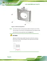
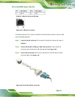
Figure 4-16: Wall-mounting Bracket
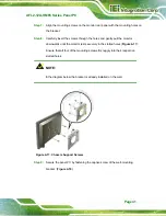
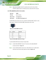
Step 6:
Insert the four monitor mounting screws provided in the wall mount kit into the
four screw holes on the real panel of the flat bezel panel PC and tighten until the
screw shank is secured against the rear panel (
6
Figure 4-17
).
WARNING:
Please use the M4 screws provided in the wall mount kit for the rear panel.
If the screw is missing, the thread depth of the replacement screw should
be not more than 4 mm.
Summary of Contents for AFL2-12A-HM65/PC-EM-R11
Page 15: ...AFL2 12A HM65 Series Panel PC Page 1 1 Introduction Chapter 1...
Page 26: ...AFL2 12A HM65 Series Panel PC Page 12 2 Detailed Specifications Chapter 2...
Page 33: ...AFL2 12A HM65 Series Panel PC Page 19 3 Unpacking Chapter 3...
Page 38: ...AFL2 12A HM65 Series Panel PC Page 24 4 Installation Chapter 4...
Page 64: ...AFL2 12A HM65 Series Panel PC Page 50 5 System Maintenance Chapter 5...
Page 73: ...AFL2 12A HM65 Series Panel PC Page 59 6 AMI BIOS Setup Chapter 6...
Page 108: ...AFL2 12A HM65 Series Panel PC Page 94 7 Software Drivers Chapter 7...
Page 130: ...AFL2 12A HM65 Series Panel PC Page 116 Appendix A A Interface Connectors...
Page 137: ...AFL2 12A HM65 Series Panel PC Page 123 B Safety Precautions Appendix B...
Page 142: ...AFL2 12A HM65 Series Panel PC Page 128 C BIOS Configuration Options Appendix C...
Page 145: ...AFL2 12A HM65 Series Panel PC Page 131 Appendix D D One Key Recovery...
Page 153: ...AFL2 12A HM65 Series Panel PC Page 139 Figure D 5 Partition Creation Commands...
Page 187: ...AFL2 12A HM65 Series Panel PC Page 173 E Watchdog Timer Appendix E...
Page 190: ...AFL2 12A HM65 Series Panel PC Page 176 F Hazardous Materials Disclosure Appendix F...