


AFL-08B-N270 User Manual
Page 103
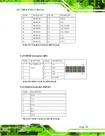
17 TFT_B2
37 GND
18 TFT_B1
38 DOTCLK
19 TFT_B0
39 GND
20 GND
40 GND
Table 5-19: TTL Panel Connector (CN7) Pinouts
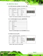
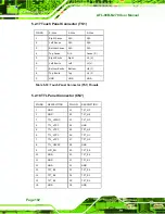
5.2.19 JUSB Connector (JUSB1)
5.2.20 USB Connector (USB1)
PIN NO.
DESCRIPTION PIN NO.
DESCRIPTION
1 +5Vsus
2 GND
3 D0F- 4 D0F+
5 D0F+ 6 D0F-
7 GND 8 +5Vsus
2
8
y
y
y
y
y
y
y
y
1
7
Table 5-21: USB Connector (USB1) Pinouts
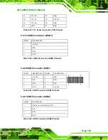
5.2.21 USB Connector (USB2)
PIN NO.
DESCRIPTION
1 +5Vsus
2 D6F-
3 D6F+
4 GND
Table 5-20: JUSB Connector (JUSB1) Pinouts
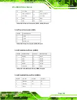
PIN NO.
DESCRIPTION
1
USB Power (selected by JP15)
2 D2F-
3 D2F+
4 GND
Table 5-22: USB Connector (USB2) Pinouts
Summary of Contents for AFL-08B-N270
Page 13: ...AFL 08B N270 User Manual Page 13 Chapter 1 1 Introduction ...
Page 22: ...AFL 08B N270 User Manual Page 22 Chapter 2 2 Installation ...
Page 52: ...AFL 08B N270 User Manual Page 52 Chapter 3 3 System Maintenance ...
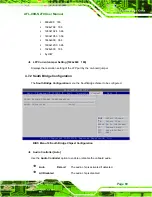
Page 59: ...AFL 08B N270 User Manual Page 59 Chapter 4 4 BIOS Options ...
Page 92: ...AFL 08B N270 User Manual Page 92 5 Interface Connectors Chapter 5 ...
Page 110: ...AFL 08B N270 User Manual Page 110 Appendix A A Safety Precautions ...
Page 115: ...AFL 08B N270 User Manual Page 115 Appendix B B BIOS Options ...
Page 118: ...AFL 08B N270 User Manual Page 118 Appendix C C ALC892 Digital Microphone Configuration ...
Page 122: ...AFL 08B N270 User Manual Page 122 Appendix D D Terminology ...
Page 126: ...AFL 08B N270 User Manual Page 126 Appendix E E Watchdog Timer ...
Page 129: ...AFL 08B N270 User Manual Page 129 Appendix F F Hazardous Materials Disclosure ...


