


AFL-08B-N270 User Manual
Page 41
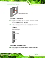
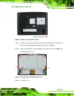
Ensure that all four of the mounting screws fit snuggly into their respective
slotted holes.
NOTE:
In the diagram below the bracket is already installed on the wall.
Figure 2-12: Chassis Support Screws
Step 9:
Secure the panel PC by fastening the retention screw of the wall-mounting
bracket. (
Figure 2-13
).
Summary of Contents for AFL-08B-N270
Page 13: ...AFL 08B N270 User Manual Page 13 Chapter 1 1 Introduction ...
Page 22: ...AFL 08B N270 User Manual Page 22 Chapter 2 2 Installation ...
Page 52: ...AFL 08B N270 User Manual Page 52 Chapter 3 3 System Maintenance ...
Page 59: ...AFL 08B N270 User Manual Page 59 Chapter 4 4 BIOS Options ...
Page 92: ...AFL 08B N270 User Manual Page 92 5 Interface Connectors Chapter 5 ...
Page 110: ...AFL 08B N270 User Manual Page 110 Appendix A A Safety Precautions ...
Page 115: ...AFL 08B N270 User Manual Page 115 Appendix B B BIOS Options ...
Page 118: ...AFL 08B N270 User Manual Page 118 Appendix C C ALC892 Digital Microphone Configuration ...
Page 122: ...AFL 08B N270 User Manual Page 122 Appendix D D Terminology ...
Page 126: ...AFL 08B N270 User Manual Page 126 Appendix E E Watchdog Timer ...
Page 129: ...AFL 08B N270 User Manual Page 129 Appendix F F Hazardous Materials Disclosure ...


