SP310
User Manual
Rev.1.0
18
Chapter 4 Interface
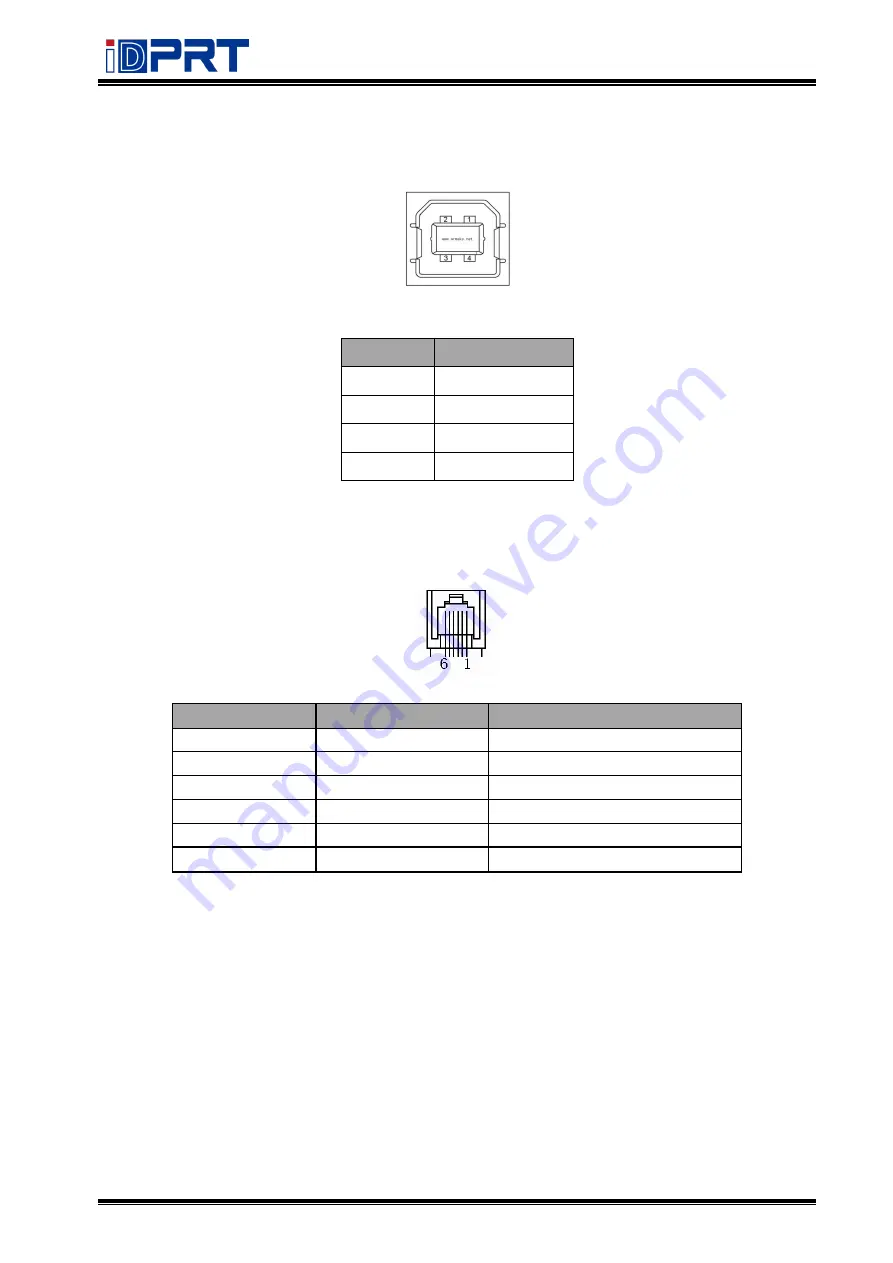
4.1 USB
I
nterface
Figure 4-1
PIN No.
Signal name
1
VBUS
2
D-
3
D+
4
GND
4.2 Cashdrawer
Pin No.
Signal
Function
1
FG
Frame Ground
2
DRAWER1
Drawer kick-out drive signal 1
3
DRSW
Drawer open/close signal
4
VDR
Drawer driving source
5
DRAWER2
Drawer kick-out drive signal 2
6
GND
GND
Voltage: 9V DC
Current:2A max.
Signal:
“
L
”
= 0
~
0.5 V ;
“
H
”
= 2.4
~
3.3 V
Summary of Contents for SP310
Page 9: ...SP310 User Manual Rev 1 0 9 1 2 Appearances and Components...
Page 10: ...SP310 User Manual Rev 1 0 10 1 3 Dimension...
Page 19: ...SP310 User Manual Rev 1 0 19 4 3 Serial Interface PIN No Signal name 1 RTS 2 RXD 3 GND 4 TXD...
Page 34: ...SP310 User Manual Rev 1 0 34 3 Speed 4 Test...
Page 35: ...SP310 User Manual Rev 1 0 35 5 Media Handling 6 Media Type...
Page 36: ...SP310 User Manual Rev 1 0 36 3 Click Watermark it recommends to use BMP format...
Page 37: ...SP310 User Manual Rev 1 0 37 4 Click Halftone Click Brightness to adjust the brightness...
Page 40: ...SP310 User Manual Rev 1 0 40 3 Click Ports then select the port according to your needs...
Page 41: ...SP310 User Manual Rev 1 0 41 4 Click Advanced to set the available time for the printer...
Page 46: ...SP310 User Manual Rev 1 0 46 4 Type in the password of your computer...
Page 48: ...SP310 User Manual Rev 1 0 48 8 Under Printer Scanner printer SP310 is available...
Page 56: ...SP310 User Manual Rev 1 0 56 Access Control Select the item for detailed setting...
Page 59: ...SP310 User Manual Rev 1 0 59 Ink Toner Levels...
Page 64: ...SP310 User Manual Rev 1 0 64 8 Click Finish...
Page 74: ...SP310 User Manual Rev 1 0 74 4 Click Next 5 Click Install...
Page 77: ...SP310 User Manual Rev 1 0 77 3 Set up the page according to your needs then click Next...


