


MSD-72 Series User’s Guide
24
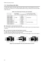
The DVI-I input connectors can be used for HDMI/DVI digital signal and other analog signal.
■
DVI signal input
Use DVI-I or DVI-D cable.
Signal only supports single-link.
■
HDMI signal input
Use HDMI-DVI conversion cable.
■
Analog RBG signal input
Use conversion cable which has DVI-I (male) and high-densed D-sub 15 (female)
■
Other analog signal input
Analog YPbPr / composite video / Y/C signal can be input.
Use conversion cable for each signal.
Pin assignments for each signal are shown below.
1
2
3
4
5
6
7
8
9
10
11
12
13
14
15
16
17
18
19
20
21
22
23
24
C2
C1
C3
C4
C5
[Figure 7.2] 29-pin DVI-I female connector
[Table 7.2] Pin assignments
Pin
#
Input signal name
HDMI / DVI
Analog RGB
Analog YPbPr
Composite video
Y/C
1
TMDS Data2-
N.C.
N.C.
N.C.
N.C.
2
TMDS Data2+
N.C.
N.C.
N.C.
N.C.
3
GND
N.C.
N.C.
N.C.
N.C.
4
N.C.
N.C.
N.C.
N.C.
N.C.
5
N.C.
N.C.
N.C.
N.C.
N.C.
6
DDC Clock
DDC Clock
N.C.
N.C.
N.C.
7
DDC Data
DDC Data
N.C.
N.C.
N.C.
8
N.C.
V-Sync
N.C.
N.C.
N.C.
9
TMDS Data1-
N.C.
N.C.
N.C.
N.C.
10
TMDS Data1+
N.C.
N.C.
N.C.
N.C.
11
GND
N.C.
N.C.
N.C.
N.C.
12
N.C.
N.C.
N.C.
N.C.
N.C.
13
N.C.
N.C.
N.C.
N.C.
N.C.
14
+5V Power
N.C.
N.C.
N.C.
N.C.
15
GND
N.C.
N.C.
N.C.
N.C.
16
Hot Plug Detect
N.C.
N.C.
N.C.
N.C.
17
TMDS Data0-
N.C.
N.C.
N.C.
N.C.
18
TMDS Data0+
N.C.
N.C.
N.C.
N.C.
19
GND
N.C.
N.C.
N.C.
N.C.
20
N.C.
N.C.
N.C.
N.C.
N.C.
21
N.C.
N.C.
N.C.
N.C.
N.C.
22
GND
N.C.
N.C.
N.C.
N.C.