background image

IMP-400UHD User Guide 

22 


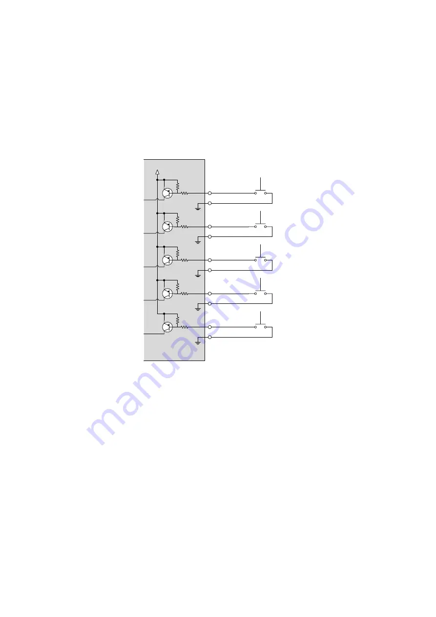
Controlling contact input 


Input channel of the IMP can be switched remotely by using contact input. 

Please ground the contact input terminal of the desired input channel to switch the input channel.   

After the GND is connected, keep it back to the open state. If using a press-type switch to control contact 

input, select a toggle type switch (pressing: ON; releasing: OFF). 


If chattering makes the operation unstable, set the removing chattering time longer   

in 

8.6.1 Chattering reduction


5V

IN1 C

IN2 C

IN3 C

G

G

Press-type 

switch

IN4 C

G

G

OFF C

G

IMP-400UHD


[Fig. 6.5] Circuit example of contact input 


Notes: 


Keep unused contact input terminals open. 


For electrical control, the range should be 0 V to 5 V ± 5 %. 


For controlling signal to contact input, please input pulse signal.   


Summary of Contents for IMP-400UHD

Page 1: ...Ver 2 2 0 Thank you for choosing our product To ensure the best performance of this product please read this user guide fully and carefully before using it and keep this manual together with the prod...

Page 2: ...Microsoft Windows Internet Explorer are either registered trademarks or trademarks of the Microsoft Corporation in the United States and other countries The terms Mozilla and Firefox and their logos...

Page 3: ...ss A digital device pursuant to part 15 of the FCC Rules These limits are designed to provide reasonable protection against harmful interference when the equipment is operated in a commercial environm...

Page 4: ...if the warning is ignored or the product is handled incorrectly Indicates the presence of a hazard that may cause minor personal injury or property damage if the caution is ignored or the product is h...

Page 5: ...ay cause the connection to overheat increasing the risk of electrical shock or fire Do not use a damaged plug or connect to a damaged outlet Unplug the product from the AC power source during installa...

Page 6: ...he product is damaged by falling or having been dropped If you continue to use the product under these conditions it may increase the risk of electrical shock or fire For maintenance and repair contac...

Page 7: ...outside the specified range for temperature and humidity continuously it may increase the risk of fire or electric shock Do not place the product at elevations of 1 24 mi 2 000 m or higher above sea l...

Page 8: ...ow to use WEB menu 31 7 2 3 Selecting input channels 32 7 2 4 Locking and Unlocking input channel selection keys 33 7 2 5 Setting sequence switching mode 34 7 2 6 Changing name of input channel select...

Page 9: ...8 3 Setting parity check 71 8 8 4 Setting stop bit 71 8 9 LAN 72 8 9 1 Setting TCP port number 72 8 9 2 Setting IP address 73 8 9 3 Setting Subnet mask 73 8 9 4 Displaying MAC address 73 8 10 Startup...

Page 10: ...IMP 400UHD User Guide 10 9 2 4 The number of TCP IP connections 91 10 Product Specification 92 11 Troubleshooting 94...

Page 11: ...ted below are included in the package If any items are missing or damaged please contact IDK One 1 main unit IMP 400UHD One 1 AC adapter with screw lock Five 5 cable clamps One 1 5 pin terminal block...

Page 12: ...C and LAN ports Contact inputs tally outputs enable the IMP to be controlled from the PC I O board and a control box EDID emulator IMP 400UHD Analog audio L R balanced unbalanced Output 1 Up to 98 ft...

Page 13: ...ble supporting 18 Gbps transmission is used Anti snow Audio De embedding Control input RS 232C LAN Contact closure Others EDID emulation All functions and configuration settings accessible through bro...

Page 14: ...ed Does not illuminate Lock is released See 7 1 2 Locking and Unlocking input channel selection keys SEQUENCE LED Shows execution status of sequence switching mode Illuminating green Being executed Do...

Page 15: ...at is input from an HDMI input connector will be converted and output LAN port For external control using communication commands or built in Web pages RS 232C port For external control using communica...

Page 16: ...layer Blu ray player Blu ray player HDMI DVI Up to 39 ft 12 m LAN 4K Monitor Controller PC Tally output Power output HDMI DVI Up to 39 ft 12 m HDMI DVI Up to 39 ft 12 m HDMI DVI Up to 39 ft 12 m HDMI...

Page 17: ...ing precautions Do not stack or place one IMP directly on top of another IMP Do not block vent holes To provide adequate ventilation maintain sufficient clearances around the IMP 1 2 in 30 mm or more...

Page 18: ...cks before handling signal cables Failure to observe this precaution may result in ESD electrostatic discharge damage Power all units off before connecting cables Be sure to fully seat all plugs and c...

Page 19: ...CbCr 4 2 2 YCbCr 4 2 0 4K Format 24 bit 30 bit 36 bit 24 bit 30 bit 36 bit 24 bit 30 bit 36 bit 3840x2160p 24 25 30 10 2 Gbps 18 Gbps 18 Gbps 10 2 Gbps 10 2 Gbps 10 2 Gbps 4096x2160 24 25 30 10 2 Gbps...

Page 20: ...nector Notes The output level of balance signal connection is twice as much as that of unbalanced signal connection When input level of digital audio is 0 dBFS output levels of analog audio unbalanced...

Page 21: ...rrent limiting resistor 2 LED75 DC 5 V output with 75 current limiting resistor 3 VCC 5V DC 5 V output 500 mA rated IN1 C Contact input When 0V GND is input IN1 will be selected G GND T Tally output W...

Page 22: ...press type switch to control contact input select a toggle type switch pressing ON releasing OFF If chattering makes the operation unstable set the removing chattering time longer in 8 6 1 Chattering...

Page 23: ...tes Keep unused contact input terminals open Before using DC 5 V output and current limiting resistor check the specification of the LED The maximum load capacity of Tally output is DC 48 V 1 A Cablin...

Page 24: ...to country The AC plug can be removed from the AC adapter Removing AC plug Slide the AC plug from the AC adapter while holding down the portion mentioned below Fig 6 8 Removing AC plug Example Plug ty...

Page 25: ...ing input channel selection keys Y Y Y Setting sequence switching mode Y Y Y Changing EDID resolution Y Y Y Setting buzzer tone of input channel key N Y Y Saving settings Loading N Y N Initializing se...

Page 26: ...put channels Press the desired input channel selection key to the output video and audio signals Press the OFF key to disable video and audio signal output Disables output Outputs IN1 input signal Fig...

Page 27: ...ed input channel selection keys cannot be operated except for IN1 which is used for unlocking Press and hold IN1 for 3 seconds or longer to unlock the key When a key is unlocked you hear a long beep t...

Page 28: ...ing enabled Does not illuminate Sequence switching disabled Fig 7 3 Setting sequence switching mode Communication Command GST SST Sequence switching mode See 8 2 4 Sequence switching mode 7 1 4 Initia...

Page 29: ...s Setting sequence switching mode Initialization Changing name of input channel selection buttons Displaying version Setting buzzer of input channel selection buttons JavaScript is used for WEB browse...

Page 30: ...bar in order to display the WEB menu See 8 9 2 Setting IP address See 8 9 1 Setting TCP port number Table 7 3 Values to be typed Control port number of web browser IP address 80 Normal http 192 168 1...

Page 31: ...ntrols see the table below Table 7 4 Menu page item Form control Display example Description Set execution button Executes the desired operation Pull down list Selects a setting value from multiple se...

Page 32: ...t Outputs IN1 input signals Disables output Fig 7 8 Selecting input channel Tip Once the input channel with HDCP is selected the HDCP authentication status of the channel is kept The switching time ca...

Page 33: ...nt keys The button will light green Operations cannot be performed from the keys while they are locked except for IN1 for unlocking the keys Click OPERATION LOCK again to unlock the front keys Lights...

Page 34: ...e desired interval Click SEQUENCE MODE to switch input channels according to the AUTO SWITCHING settings The button will light green Click SEQUENCE MODE again to disable the sequence switching mode Se...

Page 35: ...or less Click SET to rename the button Click NAME EDIT Video3 Video3 video 1 VIDEO_2 video 4 Video 1 video 1 VIDEO_2 video 4 Fig 7 11 Changing button name 7 2 7 Setting buzzer of input channel select...

Page 36: ...Setting automatic reload time of WEB menu OTHERS AUTO RELOAD TIME OFF Not reloaded the WEB menu automatically Default 1 to 10 sec Reloaded the WEB menu automatically at the selected interval Fig 7 13...

Page 37: ...lick BACKUP to save the settings After the message is displayed click OK The settings will be saved as imp 400uhd idm Click Choose File to select the desired file and click RESTORE Click OK on the com...

Page 38: ...on the confirmation message Initializing all settings including LAN setting OTHERS INITIALIZE ALL INITIALIZE Click OK on the confirmation message Note that once settings are initialized they cannot b...

Page 39: ...IMP 400UHD User Guide 39 7 2 11Displaying version You can view the model name and firmware version from OTHERS VERSION Fig 7 16 Displaying version Communication Command GIV Version...

Page 40: ...tion 7 3 1 From channel selection keys EDID changing mode Press and hold IN3 IN4 and OFF keys for five seconds until you hear the beep tones in order to select 2160p 60 3840x2160 4 4 4 or 1080p 60 192...

Page 41: ...Press the desired turned on input channel selection key Changing EDID Flashing 1080p 60 1920x1080 Turned ON 2160p 60 3840x2160 4 4 4 Fig 7 19 Changing EDID resolution Tip To select a resolution other...

Page 42: ...for 10 seconds the EDID changing mode will be disabled Note When EDID changing mode is disabled the previous and current channels may not be the same In such cases select the desired channel again 7 3...

Page 43: ...ut detection Only input channels in which video signal is detected will be switched 53 Start channel of sequence switching mode Starts from the current input channel 54 Input settings Non signal input...

Page 44: ...ength 8 Parity check NONE Stop bit 1 70 LAN Setting IP address 192 168 1 199 73 Setting Subnet mask 255 255 255 0 73 Setting TCP port number Connections 1 to 4 1100 Connections 5 to 7 23 72 Displaying...

Page 45: ...on keys Setting sequence switching mode Changing name of CHANNEL SELECT buttons 32 to 35 AUTO SWITCHING Automatic input channel switching Sequence switching mode 46 INPUT SETTING Input settings 55 to...

Page 46: ...ng 47 AUTO SWITCHING OFF AUTO SWITCHING MASK Masking time after automatic switching 50 AUTO SW BLACK DISPLAY Video to be output when input channel is changed OFF to ON 50 Sequence switching mode Table...

Page 47: ...utton flashes from when the input signal is detected to when the channel is switched automatically or suspended When the input signal become from OFF to ON and that input channel has higher priority t...

Page 48: ...nges from ON to OFF the INPUT SIGNAL LED turns off and no signal is input for 3 seconds the input channel will be switched automatically as one of the following case The input channel selection button...

Page 49: ...nal ON OFF IN 4 IN 3 IN 2 IN 1 PRI 1 PRI 1 PRI 1 PRI 1 PRI 1 PRI 1 PRI 1 PRI 1 Input signal ON OFF Input signal ON Fig 8 5 Input channel OFF to ON The priority PRI is not the same Input signal ON OFF...

Page 50: ...switched automatically to when the next automatic switching is executed Input channel is not switched during the set time 8 2 3 Video to be output when input channel is changed OFF to ON Menu AUTO SWI...

Page 51: ...ence page Remarks Target channels IN1 ON IN2 ON IN3 ON IN4 ON 8 2 5 If sequence switching mode is set to OFF the switching condition can be set Interval 10 sec 8 2 6 No video signal is input Input cha...

Page 52: ...rom IN1 Time Switching starts from The current input channel NOW CHANNEL The current channel IN2 IN2 IN3 IN4 IN1 IN3 Starting sequence switching mode Switching channel IN1 10 sec 10 sec 10 sec 10 sec...

Page 53: ...SWITCHING SEQUENCE INTERVALTIME Setting value 10sec to 30sec Default 10 sec Communication Command GIT SIT Switching interval for sequence switching mode You can set switching interval of sequence swi...

Page 54: ...urrent input channel Default FIRST CHANNEL Starts with the lowest number channel of target channels Communication Command GSC SSC Starting channel of sequence switching mode The sequence switching mod...

Page 55: ...nput settings You can set input settings from INPUT SETTING Fig 8 8 INPUT SETTING menu Table 8 5 Sub menu and feature Sub menu Feature Page INPUT VIDEO DETECT Non signal input monitoring 56 HDCP INPUT...

Page 56: ...ce to output video signal Fig 8 9 Monitoring absence of input Notes If you are using the monitor power saving or dual monitor features on your PC set this feature to OFF This will avoid unpredictable...

Page 57: ...compliant if it is connected to a display device that does not support HDCP video may not be displayed Under these circumstances and if the content is not protected the problem can be solved by setti...

Page 58: ...8 8 4 Output settings Fig 8 12 OUTPUT SETTING menu Table 8 6 Sub menu and feature Sub menu Feature Page OUTPUT MODE Output mode 59 OUTPUT HDMI MODE Checking Sink device s EDID 60 HDCP AUTHORIZATION HD...

Page 59: ...u can set a color space to be output to a sink device Normally the sink device automatically selects the optimal color space to the color space of the input video However if the sink device cannot sel...

Page 60: ...h HDMI or DVI and then outputs video signal However if the IMP cannot acquire EDID for any reason audio may not be output because the sink device s type cannot be determined correctly The desired sign...

Page 61: ...DIO menu Table 8 7 Sub menu and feature Sub menu Feature Page OUTPUT MUTE Mute 61 8 5 1 Mute Menu AUDIO OUTPUT MUTE Setting value ON Mute ON OFF Mute OFF Default Communication Command GAM SAM Audio ou...

Page 62: ...CT INPUT Chattering is an undesirable phenomenon caused immediately after contact of relay or switch is switched You can set the chattering reduction time If the IMP is unstable due to chattering set...

Page 63: ...Fig 8 16 EDID menu Table 8 9 Sub menu and feature Sub menu Feature Page PC RESOLUTION EDID resolution 64 DEEP COLOR INPUT Deep Color 67 AUDIO FORMAT Audio format 67 SPEAKER Speaker configuration 68 M...

Page 64: ...was connected before will be applied COPY EDID Copied EDID If no data is acquired previous setting immediately before selecting copied EDID is kept SVGA 800x600 SVGA 800x600 VESA XGA 1024x768 XGA 102...

Page 65: ...4 4 2160p 50 59 94 60 4 4 4 3840x2160 UHDTV YCbCr 4 2 0 YCbCr 4 2 2 YCbCr 4 4 4 supported Default 4096x2160 60 4 4 4 4096x2160 50 59 94 60 4 4 4 4096x2160 DCI YCbCr 4 2 0 YCbCr 4 2 2 YCbCr 4 4 4 supp...

Page 66: ...Y N Y Y Y N Y Y Y N N N N N N N N N N N N N N N 1600x900 Y Y Y N Y N Y Y Y N Y Y Y Y N N N N N N N N N N N N N N 1600x1200 Y Y Y N Y N Y Y Y N Y Y Y Y Y N N N N N N N N N N N N N 1680x1050 Y Y Y N Y...

Page 67: ...9 94 60 Hz YCbCr 4 4 4 24 bit pixel 8 bit component is selected automatically regardless of the setting of this menu 8 7 3 Audio format Menu EDID AUDIO FORMAT Setting value Table 8 12 Audio format Com...

Page 68: ...han EXTERNAL or Copied EDID in 8 7 1 EDID resolution Table 8 13 Default speaker configuration The number of speakers FL FR LFE FC RL RR RC FLC FRC RLC RRC FLW FRW FLH FRH TC FCH 1 OFF OFF ON OFF OFF O...

Page 69: ...00UHD User Guide 69 8 7 5 Copying EDID Menu EDID MONITOR EDID COPY Communication Command RME EDID copy EDID of the sink device is loaded and registered to the IMP The EDID can be treated as a built in...

Page 70: ...Page BAUD RATE Setting Baud rate 70 DATA BIT LENGTH Setting data bit length 71 PARITY Setting parity check 71 STOP BIT Setting stop bit 71 8 8 1 Setting Baud rate Menu RS 232C BAUD RATE Setting value...

Page 71: ...bit Default 7 7 bit Communication Command GCT SCT RS 232C 8 8 3 Setting parity check Menu RS 232C PARITY Setting value NONE Default EVEN ODD Communication Command GCT SCT RS 232C 8 8 4 Setting stop b...

Page 72: ...mask 73 MAC ADDRESS Displaying MAC address 73 8 9 1 Setting TCP port number Menu LAN PORT NUMBER Setting value Table 8 16 TCP port number Communication Command GLP SLP TCP port number Table 8 16 TCP...

Page 73: ...lue 192 168 1 199 Default Communication Command GIP SIP IP address 8 9 3 Setting Subnet mask Menu LAN SUBNET MASK Setting value 255 255 255 0 Default Communication Command GSB SSB Subnet mask 8 9 4 Di...

Page 74: ...00UHD User Guide 74 8 10Startup settings Fig 8 21 POWER ON SETTING menu Table 8 17 Sub menu and feature Sub menu Feature Page STARTUP CHANNEL Start up input channel 75 OPERATION LOCK Keylock at startu...

Page 75: ...channel that is set OFF OFF LAST CHANNEL Last channel 8 10 2Keylock at startup Menu AUDIO OUTPUT MUTE Setting value AUTO The same setting as it was before powering on the IMP Default UNLOCK LOCK Commu...

Page 76: ...re Sub menu Feature Page BUZZER Buzzer tone 76 AUTO RELOAD TIME Setting automatic reload time of WEB menu 36 BACKUP RESTORE Backing up Restoring settings 37 INITIALIZE Initialization 38 VERSION Displa...

Page 77: ...IMP 400UHD User Guide 77 8 11 2Displaying version Menu OTHERS VERSION Communication Command GIV Version You can display the IMP firmware version...

Page 78: ...b menu Fig 8 23 Displaying status menu Table 8 21 Sub menu and feature Sub menu Feature Page INPUT STATUS Input signal status 79 MONITOR STATUS Sink device status 82 ERROR STATUS Displaying error mess...

Page 79: ...I input connector Table 8 22 Input video signal format Item Value Description FORMAT 3840x2160p 59 94Hz SDTV HDTV UHDTV signal is input Format type and vertical synchronous frequency is displayed 800x...

Page 80: ...4 YCbCr 4 4 4 signal is input YCbCr 4 2 0 YCbCr 4 2 0 signal is input Table 8 26 Color depth of input video signal Item Value Description DEEP COLOR 24 BIT COLOR 24 bit pixel 8bit component signal is...

Page 81: ...nnels Item Value Description CHANNEL 2 CHANNEL 2 channel audio is input MULTI CHANNEL Multi channel audio is input Table 8 30 Speaker configuration of input audio channels Item Value Description SPEAK...

Page 82: ...connected HDCP NOT SUPPORT Non HDCP compliant sink device is connected or input signal is without HDCP HDCP ERROR HDCP compliant sink device is connected but the authentication failed HDCP CHECK NOW S...

Page 83: ...ecessary for video output Dot Clock Over The IMP does not support the input signal Channel OFF Input channel is set to OFF Table 8 36 Digital audio error message Item Value Description DIGITAL AUDIO E...

Page 84: ...evice is connected No Signal No audio signal is input AV Mute Received Audio output of source device is muted Not AUDInfoFrame The source device does not output packet that is necessary for audio outp...

Page 85: ...parameter will be displayed RESOLUTION 1920x1080 148 50MHz HDMI DVI HDMI MODE DVI MODE HDMI MODE If the sink device does not support HDMI DVI MODE is displayed COLOR SPACE 1 RGB YCbCr422 YCbCr444 YCb...

Page 86: ...ot Supported Supported If compressed audio is supported Supported is displayed HDR 3 ON ON If HDR is supported ON is displayed SCDC 3 ON ON If SCDC is supported ON is displayed 1 Displayed only if a s...

Page 87: ...communication 9 1 1 Connecting RS 232C cable See 6 3 3 Connecting RS 232C cable for connecting RS 232C cables 9 1 2 RS 232C communication specification Table 9 1 RS 232C specification Standard RS 232C...

Page 88: ...g Baud rate 3 For the control device set the same values in the same way as RS 232C communication baud rate data bit length parity check and stop bit in step 2 above 4 Send a communication command fro...

Page 89: ...X N C N C Received Data Received Data Transmitted Data Not connected Transmitted Data Not connected Not connected Not connected MDI X 8 1 LAN connector 8 pin RJ 45 connector Rear panel Lights in green...

Page 90: ...nce User Guide 3 Establish the connection from the control device to the IP address and TCP port that are set to the IMP in step 2 above 4 Send a communication command from the control device to the I...

Page 91: ...rings are issued This approach enables eight or more control devices to be effectively interfaced simultaneously and without concern for communication errors Table 9 3 Increasing connections Your PC s...

Page 92: ...utput impedance 50 Reference level 4 dBu Reference level 10 dBu Max output level 16 dBu Max output level 10 dBu Connector 1 5 pin terminal blocks Maximum cable distance Digital Input 1080p 60 98 4 ft...

Page 93: ...ut 4K 60 18 Gbps hi speed transmission cable was used and signals of 4K 60 24 bit pixel 8 bit component was input or output The maximum distance depends on connected devices If IDK s cable is not used...

Page 94: ...o is not output Check the error code in 8 12 2 Sink device status Error code 2 Check if the source device is connected and powered on Error code 3 Signal is not input Check 1 to 5 on the next page Err...

Page 95: ...rs only when a specific input is selected the problem was caused by the input side If it occurs for all inputs or only when a test pattern is displayed the problem was caused by the output side Change...

Page 96: ...first check the error code in 8 12 2 Sink device status The IMP has multiple output connectors Find the error code of the output connector that does not output audio Error code 1 Set 8 5 1 Mute to OF...

Page 97: ...put audio format supported by the connected sink device or AV amplifier input LCD monitors especially may not output 88 2 kHz or higher sampling frequency of linear PCM and compressed audio such as Do...

Page 98: ...e PC to the IMP cannot be performed Are the following items set correctly For RS 232C baud rate and data length For LAN IP address and subnet mask 70 72 ERR 6 is returned Immediately after start up th...

Page 99: ...203 204 2445 Email sales idkav com URL http www idkav com Europe IDK Europe GmbH Lise Meitner Str 6 D 40878 Ratingen TEL 49 2102 578 301 0 Email info idkav eu URL http www idkav com Product informatio...

Reviews: