FDX-32 Users Guide
25
6.2.3 Fiber optic cable
To ensure the best performance of the FDX, select the appropriate optical fiber cable for a long- distance
transmission and connect it correctly.
● Make sure that the fiber optical cable to be connected between the FDX and transmitter/receiver
meets the standard of the desired extension distance.
● Make sure not to exceed the allowable tension and bend radius of fiber optic cable or the performance
of the product and the life of the fiber optic cable may be affected.
● Extension distance varies depending on attenuation of the fiber, connector and other contact portions.
● Plug the dust caps to both faces of the fiber optic cable when connecting the fiber optic cable and
when not in use.
● Before inserting a fiber optic cable, make sure there is no damage or dirt on the end-face of the optical
connector. Clean up it or FDX-32 may not operate correctly.
● To polish connectors:
For SFP module for multimode: PC polishing is recommended.
For SFP module for singlemode: UPC polishing is recommended.
*APC polishing is not supported.
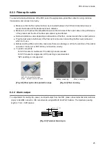
Left:With protection caps
Right:Without protection caps
Before cleaning
After cleaning
[Fig. 6.3] Fiber optic cable protection caps
[Fig. 6.4] Fiber cleaning
6.2.4 Alarm output
To output alarm for cooling fan, power, and input/output from the FDX, pleas connect attached terminal block
(2-pin) to ALARM connector. IDK recommends using AWG 28 to AWG 16 cables. The maximum pealing
length is 7 mm / 0.28
” approx.
Max. 7 mm / 0.28" approx.
[Fig. 6.5] Terminal block 2-pin


