background image

IDEMIA DOCUMENT 

– REPRODUCTION AND DISCLOSURE PROHIBITED  

RS-485 Communication

293732943-F

11

Step

three

 :

 c

omm

unic

at

ion

s

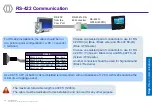
RS-232 
from the 
Com Port

RS-232 to RS-
485 converter RS-485 to 

1200m (4000ft)

RS485

16

R / 485_TX/RX+ (Y)

Green / Black

18

RS422_TX- / 485_TX/RX- (Z)

Green / White

19

RS422/485_GND

Black / Red

For RS-485 installations, the cable should be run in a 
daisy-chain configuration (i.e. converter > position 1 > 
position 2 > position 3, etc.).

Choose one twisted pair of conductors to use for 
RS-485 TX/RX+(Y) (Green / Black wire) and RS-485 
TX/RX-(Z) (Green / White wire).

Another conductor should be used for Signal 
Ground (Black / Red Wire) .

Use CAT-5 UTP (or better) cable (shielded recommended) with a impedance of 120 

. AWG 24 should be the 

minimum wire gauge used.

Choose a RS-232 to RS-485 converter that supports Sense Data to switch from Send to Receive mode.

A maximum of 31 devices may be installed on the same line. 

The maximum total cable length is 4000 ft. (1200m). 

The cable must be dedicated to this installation and not used for any other purpose

Summary of Contents for SIGMA Series

Page 1: ...All descriptions illustrations and specifications in this brochure should be considered approximate and may relate to optional equipment or feature Quick User Guide SIGMA Series...

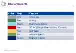
Page 2: ...DUCTION AND DISCLOSURE PROHIBITED Table of Contents 293732943 F 2 Color Step Content One Overview Two Wiring Three Communications Four SDAC Single Door Access Control Five Software Six Administration...

Page 3: ...and PIN authentication options USB port for configuration and settings with a USB mass storage key Step one overview USB host port WR product comes with a sensor protection cap not displayed here 5 W...

Page 4: ...tation is provided in Adobe Acrobat format PDF Adobe Acrobat Reader is available at http www adobe com Product packaging checklist Micro SD card must be installed in the terminal at start up storage a...

Page 5: ...gnation Biometrics Fingerprint iCLASS MIFARE DESFire Prox Water Resistant SIGMA SIGMA iClass SIGMA Multi SIGMA Prox The SIGMA Series contains the following product variants Contactless Smart card read...

Page 6: ...An Alarm 3rd party product The terminal sends a message to the Access Controller to activate the Alarm as soon as a malicious activity such as tamper or pulling is detected To secure an access IDEMIA...

Page 7: ...rminal through network commands Access control triggering event A user places a finger on the biometric sensor A user places a contactless card in front of the reader 1 Both Identification and Authent...

Page 8: ...ct exposure of the biometric sensor to sunlight or to UV lights Outdoor installations recommendations Outdoor devices shall not encounter extreme weather such as torrential rains harvest rains floodin...

Page 9: ...2 GPO1 Yellow Red 14 GPO2 Yellow Black Power supply Tamper switch Relay 1 Power 12V Red 2 Power GND Black 3 SWITCH_PIN1 Light Blue 4 SWITCH_PIN2 Pink 5 RLY_NO Yellow White 6 RLY_COM Grey White 7 RLY_N...

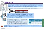
Page 10: ...ed 2 Power GND Black External Power Supply 12 24 Volts regulated and filtered 1 Amp min 12V CEE EEC EN60950 standard compliant A12 Volts power supply compliant with SIA s Wiegand standard will also be...

Page 11: ...n 2 position 3 etc Choose one twisted pair of conductors to use for RS 485 TX RX Y Green Black wire and RS 485 TX RX Z Green White wire Another conductor should be used for Signal Ground Black Red Wir...

Page 12: ...n a point to point configuration i e PC converter terminal Choose one twisted pair of conductors to use for RS 422 RX A Blue Black wire and RS 422 RX B Blue White wire Choose one twisted pair of condu...

Page 13: ...ddress 192 168 1 10 Gateway IP address 192 168 1 254 Sub network mask 255 255 254 0 Host name MAsigma RJ 45 Ethernet connection Ethernet connection to the terminal is made through a standard RJ 45 con...

Page 14: ...ree conductor wire shielded recommended is required for Data 0 Data 1 and WGND Use 18 22 AWG cable in a homerun configuration from each unit to the Access Control Panel ACP Connect WIEGAND_OUT0 Green...

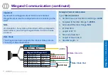
Page 15: ...Out Wiegand IN Wiegand OUT 22 WIEGAND_IN0 Green Red 23 WIEGAND_IN1 White Red 20 WIEGAND_GND Black Red 24 WIEGAND_OUT0 Green 21 WIEGAND_OUT1 White 25 WIEGAND_LEDOUT1 Blue 26 WIEGAND_LEDOUT2 Blue Red G...

Page 16: ...tton GP IN OUT 8 GPIO_GND Black Red 9 GPI0 Orange 11 GPI1 Orange Red 13 GPI2 Orange Black 10 GPO0 Yellow 12 GPO1 Yellow Red 14 GPO2 Yellow Black Relay 5 RLY_NO Yellow White 6 RLY_COM Grey White 7 RLY_...

Page 17: ...of the device Relay mode can be changed to normally close instead of normally closed default Relay 5 RLY_NO Yellow White 6 RLY_COM Grey White 7 RLY_NC Orange White Inductive load management requires...

Page 18: ...CUMENT REPRODUCTION AND DISCLOSURE PROHIBITED 18 Step five software Terminals are compatible with MorphoManager application version 15 5 or higher 293732943 F Software for Remote Administration and En...

Page 19: ...ettings terminal administration password modification Boot assistant at next boot Display this screen on next boot Protocol Settings select communication protocol Bioscrypt 4G terminals MA 500 and J S...

Page 20: ...2 Configuration with a script hosted on a USB dongle not possible Webserver disabled The terminal with firmware version 4 12 or higher has a default configuration enforcing security The default config...

Page 21: ...on TLS for secure communication The communication configuration can be done MorphoBioToolBox This Windows application can also be used for the full terminal configuration Starting from version 16 Morp...

Page 22: ...e User s face for biometric check User s administration rights none database full limited database User s PIN for PIN check User s access schedule and holiday schedule User s dynamic message setting D...

Page 23: ...y but ergonomically more difficult to use Step seven capture basics 2 Fore Finger Ring Finger 1 3 Fingerprint image too dark the finger is probably too moist and or too dusty too moist dry the finger...

Page 24: ...DEAL POSITION Incorrect Position Do not place the finger tip on the bottom of the sensor or in the middle of the sensor Correct Position Align centre of finger tip with sensor centre Incorrect Positio...

Page 25: ...POSITION Finger rotation IDEAL POSITION Incorrect Position Do not leave the finger in the air Do not bend finger upward or downward Correct Position Finger is parallel to sensor surface Incorrect Posi...

Page 26: ...uthentication process is initiated by the detection of a user card by the optional contactless card reader The terminal reads the user data stored in the card at least the User ID and starts the authe...

Page 27: ...ed to regularly backup the local database and at least after significant changes in the database add remove or modification of user s records on a external support such a mass storage key Date Time sy...

Page 28: ...overview of the product and the basics of configuration and use Administration Guide This document describes the different functions available on the terminal and the procedures for configuring the t...

Page 29: ...om Tel 1 714 575 2973 EMEA Europe Middle East Africa Mail support bioterminals idemia com Tel 33 1 30 20 30 40 For the latest firmware software document releases and news please check our website http...

Reviews: