


2 Operational Check
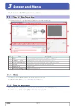
3 Screen and Menu
4 Appendix
1 Overview
2-4
Operation Confirmation Method
z
RS-232 connection
When using the communication unit
Wire the WB2F to the PC as shown in the diagram. After you finish wiring the WB2F and PC, turn on the 24-VDC power
supply.
If the PC is not equipped with a RS-232 port, please use a RS-232-to-USB conversion cable.
2
RXD
Pin Number
Description
3
TXD
7
RTS
8
CTS
5
GND
1
DCD
4
DTR
6
DSR
9
RI
Description
SD
RD
CS
RS
SG
Input/Output/RS-232/RS-422 port
Connector for Input/Output/
RS-232/RS-422 port
Connector for Input/Output/
RS-232/RS-422 port
Host device
D-sub 9-pin connector
Do not reverse the power supply connections under any circumstances. Doing so may result in damage. Care-
fully read the user’s manual for the communication unit before wiring the WB2F.
When not using the communication unit
Wire the WB2F to the PC as shown in the diagram. After you finish wiring the WB2F and PC, turn on the 5-VDC power sup-
ply.
If the PC is not equipped with a RS-232 port, please use a RS-232-to-USB conversion cable.
2
RXD
Pin Number
Description
3
TXD
7
RTS
8
CTS
5
GND
1
DCD
4
DTR
6
DSR
9
RI
5V DC
Pin Number
6
Description
TXD
10
RXD
11
CTS
12
RTS
9
0V
5
+5V
D-sub 9-pin connector
WB2F
Host device
Function
RS-232 Transmission Data
RS-232 Receive Data
RS-232 Control Signal
RS-232 Control Signal
Power Supply (- SG Shared)
Power
Do not reverse the power supply connections under any circumstances. Doing so may result in damage. Care-
fully read the user’s manual for the WB2F before wiring the WB2F.


