background image

41

Systemiser SE - 

Installation

SERVICING

SER

VICING

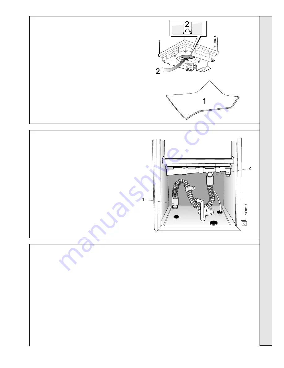
58 CLEANING THE HEAT EXCHANGER

Re-assemble the boiler in the following order:

1.

Refit the condensate trap.

2.

Refit the burner, renewing any damaged or deteriorating
sealing gaskets.

3.

Reconnect the ignition and detection leads.

4.

Reconnect the fan electrical lead.

5.

Refit the fan, engaging it in the bayonet fixing.  Ensure
that the 'O' ring seal is in place.

IMPORTANT

This MUST be done with the heat exchanger and
deposit in a DRY condition.

Prior to cleaning, run the boiler until a flow temperature
of 80 

o

C is reached - refer to Frame 52, step 1

(Servicing schedule).

1.

Place a plastic sheet or similar beneath the boiler
and remove all visible loose deposits from the heat
exchanger fins, using a suitable brush.

2.

Take care to clean debris from the ledge inside the
combustion chamber.

1.

Pull off  the condensate trap from the bottom
panel and carefully empty the contained water
into a receptacle.

2.

Pull off the trap from the bottom of the boiler.

3.

Withdraw the trap from the boiler.

4.

Thoroughly flush the trap by running high
pressure water through it.

6.

Refit the fan inlet venturi complete with sensing pipe.

7.

Refit the boiler sealing panel.

IMPORTANT.

Ensure that the boiler sealing panel is correctly fitted
and that a good seal is made.

8.

Refit the boiler casing.

9.

Turn on the gas supply at the gas service cock.

10.

Reconnect the electrical supply.

59 CLEANING THE CONDENSATE TRAP

60 RE-ASSEMBLY

Summary of Contents for Systemiser SE

Page 1: ......

Page 2: ...nnections before the boiler is fitted and it fits inside a cupboard Its compact size makes the Systemiser SE ideal for any kitchen It can be installed inside a cupboard without any ventilation Systemi...

Page 3: ...he possibility of injury during the installation servicing or cleaning of this appliance care should be taken when handling edges of sheet steel components KEY TO SYMBOLS IE Ireland Countries of GB Un...

Page 4: ...be provided in the installation pipework OPTIONAL EXTRA KITS Extension Flue Kit Pack D Roof Flue Kit for vertical flue connection Powered Vertical for extended vertical flue connection Flue Flue Elbow...

Page 5: ...temperature of between 40 o C and 82 o C Refer also to Frame 1 Boiler Water Circuit Diagram The boiler features a comprehensive diagnostic system which gives detailed information on the boiler status...

Page 6: ...TLET The boiler must be installed on a flat and vertical wall capable of adequately supporting the weight of the boiler and any ancillary equipment The boiler may be fitted on a combustible wall Insul...

Page 7: ...2871 1 is recommended for water carrying pipework and MUST be used for pipework carrying potable water Any soldered joints on potable water pipework MUST NOT be made with solder containing lead GAS S...

Page 8: ...It is most important that the correct concentration of the water treatment product is maintained in accordance with the manufacturers instruction 2 If the boiler is installed in an existing system an...

Page 9: ...talled in a room containing a bath or shower then the appliance and any electrical switch or appliance control utilising mains electricity should be so situated that it cannot be touched by a person u...

Page 10: ...ge pressure of 0 75 bar 4 Make up Water Provision must be made for replacing water loss from the system either a From a manually filled make up vessel with a readily visible water level The vessel sho...

Page 11: ...he heating circuit of load of at least 60 of the boiler output at minimum rate i e 60 of 10 1 kW 34 500 Btu s equal 6kW 21 000 Btu s must be provided with twin lockshield valves so that this minimum h...

Page 12: ...Burner 3 Gas valve 4 Detection electrode 5 Ignition electrodes 13 Fan 26 Boiler flow pipe 27 System flow pipe 30 Gas inlet pipe 35 Heat exchanger 48 Prepiping frame 16 Expansion vessel 17 Pump 18 Aut...

Page 13: ...l mounting plate z Wall mounting template z These Installation and Servicing Instructions z User s Instructions z Stand off brackets optional use 1 pair z Concealment panels optional use 1 pair Stand...

Page 14: ...RMINING THE FLUE LENGTH AND FLUE PACKS REQUIRED Dimension X Wall thickness Dimension Y Wall thickness plus boiler spacing RHS Dimension Z Wall thickness plus boiler spacing LHS Calculate the total len...

Page 15: ...LATE IMPORTANT For direct mounting piping frame on wall choose one black circle in each group If using the stand off brackets choose one dotted circle in each group Care MUST be taken to ensure the co...

Page 16: ...sonry falling outside of the building does not cause damage or personal injury 14 FITTING THE PIPING FRAME Fit the wall mounting frame either a Directly to the wall z z z z z Insert wall plugs z z z z...

Page 17: ...w straight pipe and reducing coupling together 2 Remove the gas cock bracket complete with gas cock 3 Screw the connector into the gas cock in the correct orientation 4 Screw the complete assembly bac...

Page 18: ...the boiler 18 CUTTING THE FLUE Rear Flue Length of 114 to 580mm Note If the optional standoff bracket kit is used it is essential that 80mm is added to the measured wall thickness when marking the fl...

Page 19: ...the flue turret fill the condensate trap within the boiler by pouring a cupful of water into the flue outlet A 1 Insert the flue assembly through the prepared hole in the wall far enough to allow the...

Page 20: ...dotted circle in each group Care MUST be taken to ensure the correct holes are drilled 1 Tape the template into the selected position 2 Ensure squareness by hanging a plumbline as shown 3 Mark onto t...

Page 21: ...ed around the groove provided The terminal wall plate need not be fitted 24 FITTING THE PIPING FRAME Fit the wall mounting frame either a Directly to the wall z z z z z Insert wall plugs z z z z z Put...

Page 22: ...se elbow Notes 1 Do not subject any of the isolating valves to heat as the seals may be damaged 2 In areas where the mains water pressure is known to be high greater than 10 bar it is recommended that...

Page 23: ...Add dimension H measured in Frame 22 c For right hand side flue add 188mm 7 3 8 d For left hand side flue add 61mm 2 3 8 i e X H 188mm 7 3 8 for RHS X H 61mm 2 3 8 for LHS 2 Measure from the groove an...

Page 24: ...rough the prepared hole in the wall far enough to allow the rubber seal to unfold completely and form an adequate seal on the outside wall 2 Pull the flue back and locate the flue turret on the top of...

Page 25: ...rainage pipework must be arranged so that obstruction e g through freezing of external drainage pipe does not give rise to spillage within the dwelling Excessive external pipe runs should be avoided i...

Page 26: ...socket screw The position of the safety valve discharge pipe should be such that any discharge of water or steam does not create a hazard 33 SAFETY VALVE DRAIN 35 FLUE EXTENSION DUCTS continued Pack...

Page 27: ...3 Fit the outer flue extension duct onto the outer air duct 4 Drill one 3 2mm 1 8 dia hole through the outer air duct Do not drill the inner flue duct 5 Insert the self tapping screw provided to fix t...

Page 28: ...down 3 Fill and vent the system Check for water soundness Refer also to Frame 5 INSTALLATION Front elevation layout of boiler components control panel open Legend A Boiler heat exchanger B Gas valve...

Page 29: ...the current wiring regulations and any local regulations Connection must be made in a way that allows complete isolation of the electrical supply such as a double pole switch having a 3mm 1 8 contact...

Page 30: ...ngths of the current carrying conductors are shorter than the earth conductor so that if the cable slips in its anchorage the current carrying conductors become taut before the earth conductor 3 If a...

Page 31: ...31 Systemiser SE Installation INSTALLATION INSTALLATION 42 PICTORIAL WIRING DIAGRAM...

Page 32: ...iring differs slightly see manufacturer s literature Notes 1 Some earth wires are omitted for clarity Ensure proper earth continuity when wiring 2 Numbering of terminals on thermostats is specific to...

Page 33: ...ole of the gas installation including the meter should be inspected and tested for soundness and purged 2 Purge air from the gas installation by loosening the gas cock union and purge until gas is sme...

Page 34: ...upply is OFF 4 Check that the gas service cock I is OPEN 5 Remove screw and swing the control panel down 6 Remove the screw in the burner pressure test point C and connect a gas pressure gauge via a f...

Page 35: ...ng to maximum rate 14 Test for gas soundness around ALL boiler gas components using leak detection fluid 15 Operate the boiler for 20 minutes to stabilise the burner temperature 16 The boiler central...

Page 36: ...to the boiler and drain down to complete the flushing process Note A flushing solution should be used during the flushing procedure Flushing solutions Fernox Superfloc Sentinel X300 new systems or X40...

Page 37: ...s indicated the boiler should be turned off and a registered local heating installer consulted 7 Explain and demonstrate the function of time and temperature controls radiator valves etc for the econo...

Page 38: ...contract yourself or alternatively to the customer the benefits of the Ideal Care scheme details of which are outlined in the Householder pack supplied with this boiler Note Some aluminium oxide build...

Page 39: ...OILER SEALING PANEL REMOVAL 1 Release the 2 retaining clips 2 Swing the panel open to the left and disengage it from the boiler 54 CASING REMOVAL 1 Undo the securing screw 2 Lift to disengage the casi...

Page 40: ...he boiler 5 Depress the retaining clip and rotate the fan to the right to disengage the bayonet fixing on the fan outlet 6 Draw the fan forward and unplug the electrical lead from the motor 7 Withdraw...

Page 41: ...lastic sheet or similar beneath the boiler and remove all visible loose deposits from the heat exchanger fins using a suitable brush 2 Take care to clean debris from the ledge inside the combustion ch...

Page 42: ...BOILER MUST NOT BE OPERATED IF THE SEALING PANEL IS NOT FITTED Note In order to replace components in Frames 74 to 82 it is necessary to drain the boiler Refer to Frame 73 1 Refer to Frame 61 2 Remove...

Page 43: ...ounting flange D O ring seal Note Check the spark and detection gaps Refer to Frame 39 1 Refer to Frame 61 2 Remove the boiler casing Refer to Frame 54 3 Remove the boiler sealing panel Refer to Frame...

Page 44: ...aw the electrode 7 Fit new electrodes as required ensuring that the gaskets are in good condition and are sealing correctly renew as necessary 8 Check the spark detection gaps 9 Re assemble in reverse...

Page 45: ...t pipe 10 Transfer the mounting brackets and sensing pipe to the new valve renewing any damaged or deteriorating sealing gaskets 11 Transfer the gas inlet pipe to the new valve using the new sealing w...

Page 46: ...g posts 7 Fit the new board and re assemble in reverse order Ensure that all electrical connections are correctly remade 8 Check the operation of the boiler 1 Refer to Frame 61 2 Remove the boiler cas...

Page 47: ...in reverse order Ensure that the switch is the right way round and that all electrical connections are correctly remade 8 Check the operation of the boiler 72 CONDENSATE TRAP REPLACEMENT 1 Refer to Fr...

Page 48: ...control thermistors one on the boiler flow boss and one on the return boss 1 Refer to Frame 61 2 Remove the boiler casing Refer to Frame 54 3 Drain the boiler refer to Frame 73 4 Disconnect the flexi...

Page 49: ...The new seals provided are fitted b The electrical connections are correctly remade c The pump selector switch is set at position 3 10 Check the operation of the new pump 1 Refer to Frame 61 2 Remove...

Page 50: ...the air vent 5 Unscrew the air vent from the boiler flow boss 6 Fit the new air vent complete with O ring provided and re assemble in reverse order IMPORTANT Ensure that the vent cap A is loose 1 Refe...

Page 51: ...ch from the boss in the bottom of the heat exchanger and withdraw it from the boiler 9 Fit the new switch using a suitable jointing compound and re assemble in reverse order 10 Check the operation of...

Page 52: ...e 76 12 Remove the water pressure switch hidden Refer to Frame 79 13 Undo the 2 back retaining screws 14 Disconnect the flow and return thermistor sensor leads 82 HEAT EXCHANGER REPLACEMENT continued...

Page 53: ...to Frame 54 3 Remove the boiler sealing panel Refer to Frame 55 4 Remove the old seal and thoroughly clean the panel surfaces 5 Fit the new self adhesive seals to the panel 6 Re assemble in reverse o...

Page 54: ...before lockout 84 FAULT FINDING FAULT FINDING Note To gain access to the Gas module control buttons remove the cover plate Refer to Frame 91 The boiler Gasmodul control unit is equipped with a fault...

Page 55: ...4 13 4 14 4 15 4 16 4 17 4 24 Flow and return sensors NTC1 and NTC2 reversed 4 26 Minimum gas pressure 4 30 Maximum difference between T1 and T2 exceeded 4 31 NTC1 short circuit 4 32 NTC2 short circu...

Page 56: ...CH on off switch ARCOELECTRIC 2 139 603 13 Fan assembly EBM 1 139 368 15 Safety valve CALEFFI 1 075 146 16 CH expansion vessel 1 075 142 17 Pump with gaskets GRUNDFOS UPS 15 60 1 075 139 18 379 796 Au...

Page 57: ...57 Systemiser SE Installation SHORTS LIST OF PARTS 86 SHORT PARTS LIST...

Page 58: ...njector 3 Gas valve 4 Detector electrode 5 Ignition electrode 13 Fan 14 Fan inlet venturi 19 Fan pressure sensing pipe 42 O ring 43 O ring 44 O ring 45 Gasket rubber 46 Gasket Cork 54 EV1 solenoid 55...

Page 59: ...er SE Installation SHORT LIST OF PARTS Legend 6 Gasmodul control 7 Display board 8 Fan speed control board 11 CH pressure gauge 12 Rocker switch 50 Control panel 58 Relay 88 CONTROL PANEL ASSEMBLY Exp...

Page 60: ...60 Systemiser SE Installation 89 BOILER CASING ASSEMBLY SHORT LIST OF PARTS...

Page 61: ...61 Systemiser SE Installation...

Page 62: ...pursues a policy of continuing improvement in the design and performance of its products The right is therefore reserved to vary specification without notice CaradonPlumbingLimited P O Box103 National...

Page 63: ...be giving away a free boiler for the five best ideas every year to be selected by our Technical Director Please complete this form using extra sheets if required and post it or fax it to us on 01482...

Page 64: ...e to join an Ideal factory tour Range guides required The Ideal Guide a specifier s and installer s introduction to the Ideal domestic boiler range The Ideal Householders Guide to assist the installer...

Reviews: