SERVICING
38
europa
--- Installation & Servicing
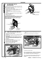
54 IGNITION PCB REPLACEMENT
1 Gain access to the parts located inside the control panel
as explained in the the frame 53.
2 Remove all the wiring connected to the ignition p.c.b.
To disconnect the connectors indicated, delicately flex the
hook present on one side of each socket.
3 Unscrew the two screws A that hold the ignition p.c.b. on
the panel and remove the component.
4 Re---assemble in reverse order.
5 Check the boiler operates correctly.
A
A
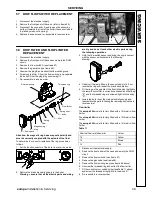
55 CH FLOW SWITCH REPLACEMENT
1 Disconnect the electrical supply.
2 Remove the front casing panel.
3 Remove the fork A.
4 Open the box B and disconnect the switch.
B
A
5 Re---assemble in reverse order.
Refer to the following illustration for the correct wiring
connectors on the switch
N.O.
do not use
C
Looking through the switch box B it is possible to verify the
position of the spindle C
C
Boiler OFF
Pump operating
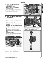
56 CH FLOW SWITCH MEMBRANE
REPLACEMENT
1 Disconnect the electrical supply.
2 Remove front casing panel (refer to frame 33).
3 Close off the isolating cocks of the CH circuit at the
bottom of the boiler.
4 Release system pressure by opening the main circuit
drainage cock.
Do not release CH pressure using the pressure relief
valve. It may cause debris within the system to foul
the valve.
5 Remove the CH circuit flow switch (see frame 55).
6 Unscrew the four screws A, open the hydraulic operator
and remove the membrane B.
7 Re---assemble in reverse order.
When assembling the membrane, ensure to place the
concave side of the membrane towards the actuator plate
C and locate the reference hole in the membrane over the
pressure transfer nipple D.
A
B
C
D
S
E
R
V
IC
IN
G


