Concord CX -
Installation
29
46 INSTRUCTIONS FOR SITE ASSEMBLED BOILERS - continued
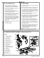
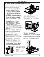
over the gas line tie bracket. Fasten
the bolt securing the bracket to the
front section before wrapping and
securing insulation around the
boiler body.
18.
Insert the burner rear supports into
the slots at the back of the
combustion chamber. Lift the front of the burners over
the injectors and pull forward to engage.
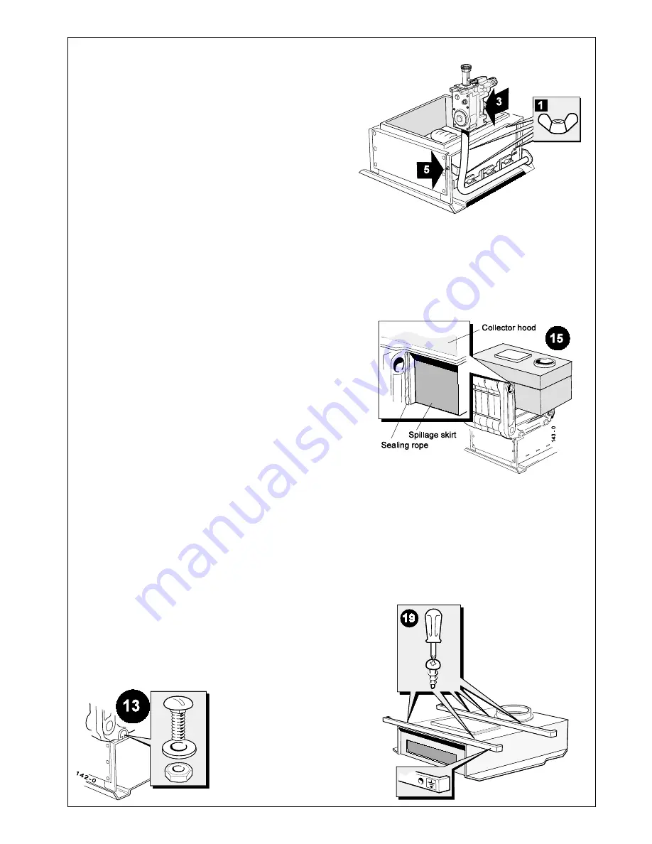
19.
Fit the support angles (contained in the platework
package) to the collector hood. The angle with the hole
for the earth screw fits to the front.
PREPARATION OF SECTIONS
Each section should be brushed clean on all external
surfaces and any debris which may have accumulated within
the section should be removed via the bottom ports.
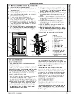
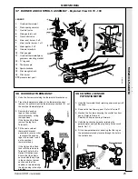
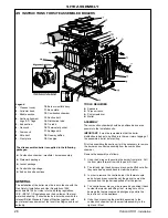
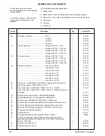
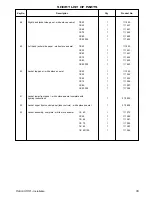
Section assembly - refer to exploded view, Frame 45
6.
Take the back section (with 1/2" BSP tappings in the top)
and lift it onto the combustion chamber so that the
combustion chamber back panel return is inside the
section rear lip. Locate a slotted steel ring and an ‘O' ring
seal into each of the 4 ports. It will be necessary to
squeeze the steel ring slightly to enable it to be pushed
fully into the recess.
7.
Lift a middle section onto the combustion chamber and
carefully offer it up to the back section until it engages the
projecting steel rings. It may be necessary to use a mallet
and hardwood block to ensure that the steel rings are
pushed fully into the recesses and that the sections are
butted up to each other.
Note.
Until the final section is fitted and the tie rods
fastened the sections in the assembly are not fixed
together therefore CARE MUST BE TAKEN TO
PREVENT the installed section coming apart.
8.
Repeat the above procedure for all of the remaining
sections until the assembly is complete.
9.
Fit the 4 tie rods through the holes in the sides of the end
sections and fit a flat steel washer, a shakeproof washer
and a nut to both ends of each tie rod. Screw up all the
nuts equally, in turn, and finally tighten them to a torque of
38-41 Nm (28-30 lb. ft.).
10.
Fit the distributor tube assembly as described in Frame 8.
Fit the drain cock (refer to exploded view in Frame 45).
11.
On open vented systems a hydraulic test should be
carried out at 1
1/2
times the design pressure given in
Table 2 for a period of 30 minutes.
12.
On a pressurised system the test should be at twice the
design pressure for a period of 30 minutes.
13.
Fit the 4 coach bolts into the lugs at the bottom of the
front and rear sections. Secure with the nuts and washers
provided.
14.
Fit the flue baffles which are located between the fins.
15.
Fit the collector hood. Ensure the underside returns
running across the hood sit within the front and rear
section flueways. Fasten down, using the four M6 screws
and nuts provided, through the front and rear fixing points.
16.
Locate the fibreglass rope in the rear section grooves to
form a seal with the spillage skirts. Fit the spillage skirts
onto the collector hood using the self tapping screws
provided.
17.
Refit the manifold assembly. Position the boiler insulation
20.
Fit the gas inlet pipe bracket to the rear support angle, on
the LH side using the self tapping screws.
21.
Fit the gas inlet pipe and make good the union between the
gas cock and the valve inlet pipe.
22.
Fit the Nox duct, using the reverse procedure to that shown
in Frame 36, and secure with the extended nuts.
23.
The boiler is now ready for installation. Go to Frame 8 in
this publication and continue the installation from there.
SITE ASSEMBLY
Summary of Contents for Concord CX40
Page 1: ......

