28
Concord CX
- Installation
45 INSTRUCTIONS FOR SITE ASSEMBLED BOILERS
The site assembled boiler is supplied in the following
packages:
z
Combustion chamber / manifold / burner assembly.
z
Platework package.
z
Jacket package.
z
Controls box package.
z
End and centre sections.
TOOLS REQUIRED
z
Spanners
z
Torque wrench
z
Pozi screwdriver
z
Mallet
ASSEMBLY
The combustion chamber should be positioned as near as
possible to the installation site.
IMPORTANT.
It must be remembered that the boiler
distribution tube has to be fitted into the rear return tapping of
the assembled boiler before siting.
Prior to assembling the sections it will be necessary to remove
the burner and controls assembly from the combustion
chamber.
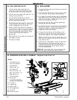
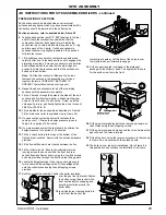
Remove the assembly as follows:
1.
Undo the 4 wing nuts securing the burner front plate. Pull
the front plate forward from the top and lift it out.
2.
The left and right hand burners may now be lifted out after
they have been pushed back to clear the injector.
3.
In order to remove the centre burner, the thermocouple
and pilot gas pipe connections at the gas valve must be
removed and the igniter lead pulled off at the igniter.
4.
The centre burner may now be removed by pushing it back
to clear the injector and lifting it out - taking care not to
damage the thermocouple and pilot gas pipe while the
burner is out of the appliance.
5.
Undo the nut securing the manifold assembly to the
combustion chamber, pull the manifold assembly to the
right and lift out.
SITE ASSEMBLY
GENERAL
The installation of the boiler must be in accordance with the
Gas Safety (Installation and Use) Regulations 1994,
amendments 1996 or rules in force, building regulations,
I.E.E. (BS.7671) Regulations and the bye-laws of the local
water undertaking. It should also be in accordance with the
relevant British Standard Codes of Practice together with
any relevant requirements of the local Gas Region and local
authority.
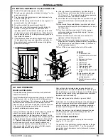
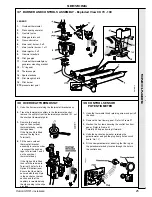
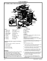
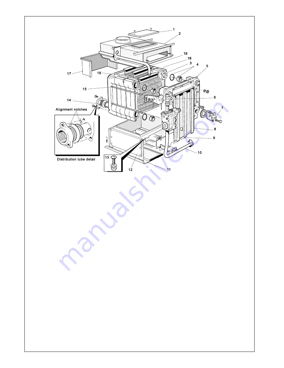
Legend
1
. Cleanout cover.
2.
Collector hood.
3.
Middle section.
4.
Section alignment
rings & 'O' rings.
5.
End section.
6.
Gas cock.
7.
Drain cock.
8.
NOx duct.
9.
Front plate.
10.
Burner manifold assy.
11.
Base plate.
12.
Combustion chamber.
13.
Section bolt.
14.
Distribution tube.
15.
Tie rods.
16.
Thermostat pocket.
17.
Spillage skirt.
18.
Flueway baffles.
19.
Gas pipe.
Summary of Contents for Concord CX40
Page 1: ......


