background image

7

Plate Heat Exchanger Package

Section 4 - Installation Requirements

4.1  INSTALLATION AREA AND    

 DIMENSIONS

Ensure adequate access for boiler and package installation. 

Ensure at least 450 mm clearance from the front of the 

appliance to allow servicing.
The condensate drain must have a 1 in 20 fall away from the 

appliance.

Adequate room above the boilers must allow the installation 

and serving of the boiler flue system. Further information 

concerning flue and condensate drain connection can be 

found in the boiler installation manual.

4.2  SYSTEM REQUIREMENTS

1. 

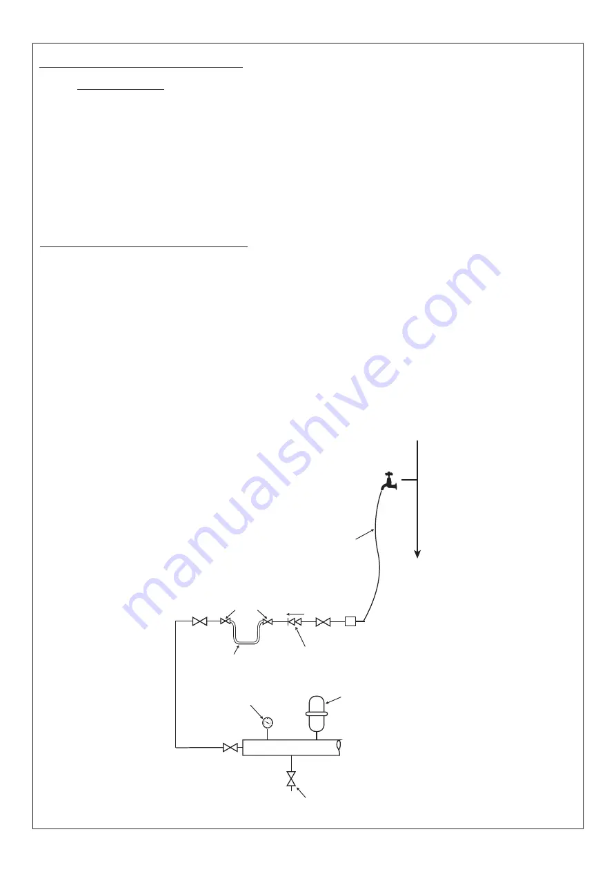
Ancillary components can be connected to the system via 

the G3/4” isolation valve on the boiler return pipework. 

See diagram below for guidance (diagram for illustration 

purposes only).

2. 

The method of filling, refilling, topping up or flushing 

sealed primary circuits from the mains via a temporary 

hose connection is only allowed if acceptable to the local 

water authority.

3. 

The filling device must be connected to comply with the 

water regulations, as shown below. This may involve fitting 

an a suitable WRAS approved isolator valve to the mains 

supply and appropriate backflow prevention device.

Pressure relief valve (Supplied with the package)

Pressure Gauge

Expansion Vessel

Drain Cock

Return

Double check valve or 

RPZ assembly 

(note direction of flow)

Additional 

stop valve

Hosepipe 

(disconnect 

after filling)

Water 

Supply

Temporary Hose 

(disconnect 

after filling)

Hose unions

G3/4” 

Valve

4. 

A spring-loaded non-adjustable 3 bar pressure relief valve 

complying with the relevant standards of BS6759 Pt1 

is fitted close to the boiler with no intervening valve or 

restriction.

5. 

A manual testing device.

6.  The safety valve outlet should be piped to ensure water or 

steam discharge cannot create a hazard to personnel or 

damage electrical components or wiring.

Pressure gauge (Supplied with the package)

A pressure gauge covering at least 0-6 bar is fitted to the 

return pipework, visible from the filling point.

Expansion vessel (Supplied with the package)

7.  A diaphragm type expansion vessel complying with BS. 

EN 13831 must be fitted, with a valve in the normally open 

positioned protected using a lockshield from unauthorised 

closure.

8.  The vessel capacity must be adequate to accept the 

expansion of system water when heated to 85 °C.

9.  The charge pressure must not be less than the static 

water head above the vessel. The pressure attained in the 

system when heated to 85 °C should be at least 0.35 bar 

less than the lift pressure of the pressure relief valve.

The 4L expansion vessel supplied is suitable for all 

appliances.
System drain cock (Supplied with the package)

A drain cock is fitted to the lowest section of the return 

pipework. A second drain cock is fitted above the NRV after 

the boiler pump.

Summary of Contents for EVOMAX 2 30

Page 1: ...e Do not use reconditioned or copy parts that have not been clearly authorised by Ideal Heating For the very latest copy of literature for specification and maintenance practices visit our website ide...

Page 2: ...kaging and product in a corresponding recycle centre Do not dispose of the unit with the usual domestic refuse Do not burn the product Remove the batteries Dispose of the batteries according to the lo...

Page 3: ...2 1 Plate Heat Exchanger Kit Options 5 2 2 Hydraulic Separation Plate Heat Exchanger 5 2 3 Output Control 5 2 4 Gas Supply 5 2 5 Safe Handling 5 Section 3 Package Contents Components 6 3 1 Package Com...

Page 4: ...arate the boiler hydraulically primary from an existing heating hot water system secondary See appliance manuals for the flue configurations for the range of appliances using this kit 150 kW boilers m...

Page 5: ...he range of available Evomax 2 boilers The kit is based on a low height frame and allows hydraulic separation of the boiler from the secondary system in a compact envelope Consider the modulation rang...

Page 6: ...PIPEWORK 001 Gas Connection Kit 002 Mounting Frame Fabrication 003 Evomax 2 Low Height 1 5 in Return 004 50 mm Square Plastic Tube Insert M12 Threaded 005 Adjustable Foot 50 x M12 x 100 006 Return Ma...

Page 7: ...PZ assembly note direction of flow Additional stop valve Hosepipe disconnect after filling Water Supply Temporary Hose disconnect after filling Hose unions G3 4 Valve 4 A spring loaded non adjustable...

Page 8: ...be bolted secured to the floor after the connections are made to the boiler or system pipework from the package to allow for minor adjustments of the position of the package MOUNTING FRAME MUST BE SEC...

Page 9: ...manual for the appliance 5 3 LEVELLING Levelling feet are provided to allow height adjustment of the package Height adjustment can be used for levelling and ensuring that connections to existing flue...

Page 10: ...e to drain following the recommendations contained in the boiler Installation instructions 5 4 6 Pressure Relief Connection Ensure the boiler pressure relief valve is connected and piped to safety 5 4...

Page 11: ...Interlock Pump control 0 10V OpenTherm Header GND S4 GND Mains Supply Demand inputs 230V 50Hz Interlock 230V 50Hz Auxiliary MFR1 MFR2 MFR3 OT2 S1 GND S2 GND S3 C OT2 C NO I0 I1 PWM GND 10V 10V GND OT1...

Page 12: ...dual boiler commissioning UPMXXL for use with Plate Heat Exchangers 1 per boiler EVOMAX 2 IMPORTANT PWM Control to be wired directly to the boiler MUST be wired in last For pump and external pump cont...

Page 13: ...Notes 13 Plate Heat Exchanger Package...

Page 14: ...Notes 14 Plate Heat Exchanger Package...

Page 15: ...Notes 15 Plate Heat Exchanger Package...

Page 16: ...deal Technical Helpline 01482 498663 Ideal Consumer Helpline 01482 498660 Ideal Parts 01482 498665 idealheating com Ideal Boilers Ltd pursues a policy of continuing improvement in the design and perfo...

Reviews: