


30
Harrier GTS -
Installation & Servicing
INSTALLATION
3
4
1
2
5
6
7
8
9
10
11
12
L
4
N
ALI
5
6
7
8
9
10
11
12
230 V / 50 Hz
N
L1
T1
T2
T6
T7
T8
S3
VA
3 x 0,75 mm
2
har7049
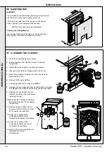
47 WIRING DIAGRAM
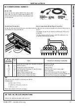
46 CONNECTING OPTIONAL FEATURES
Flow Switch / Optional Safety Devices
If a flow switch or other safety control is to be
included in the system, connect the device(s)
in series in the safety circuit, (i.e. between
terminal 5 of the connecting strip and burner
terminal L1).
Burner Alarm Indicator
If an alarm indicator is to be included it should
be connected across terminal 12 (live) and
terminal 4 (neutral).
Safety Thermostat Alarm Indicator System
1. The unused insulated terminal on the
safety thermostat may be used to connect
an alarm signal. (This terminal becomes
live if the safety thermostat trips.)
2. Remove the insulation and connect the
live wire from the alarm indicator to the
unused terminal using a suitable spade
connector and the neutral to terminal 4.
12
11
10
9
8
7
6
5
4
VA
S3 T8
T7
T6
T 2 T
1 L1
N
230V
50Hz
L
N
ALI
har7050
VA
TCH1
TCH2
N
N
TS1
ZB
ZB
DJ10A
ZTB
(B)
L1
T1
BA
BA
T2
T6
T7
T8
S3
5
BA 4
2
L
BA
3
BA 6
BA 7
BA 8
BA 9
BA 10
BA 11
BA 12
B
Burner
BA
Connection strip
DJ10A
10 A circuit-breaker
L
Live
N
Neutral
TCH1
Stage 1 boiler thermostat
TCH2
Stage 2 boiler thermostat
TS1
Safety thermostat
VA
Alarm indicator
ZB
Burner switch
ZTB
STB-Test switch
Connecting strip
*
*
Optional
Connector
har9095
INST
ALLA
TION


