34
British Gas RD1
-
Installation & Servicing
SERVICING
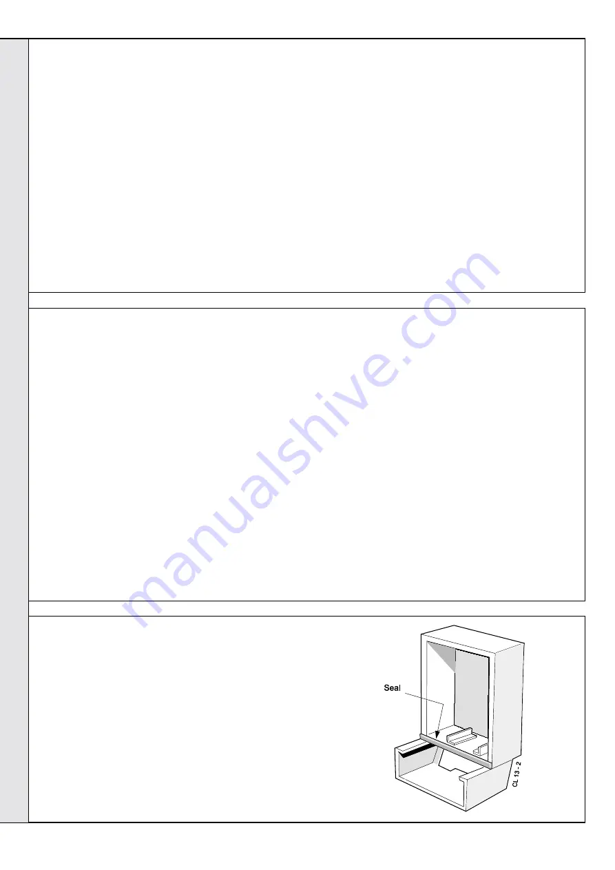
65 CASING SEAL REPLACEMENT
1. Refer to Frame 51.
2. Remove the old seal from the casing surround and
thoroughly clean the casing surfaces.
3. Fit the new self adhesive seals.
4. Replace the boiler casing.
Model RD130 does not have air deflector baffles
fitted to the casing bottom.
9. Slacken 3 turns only the 4 heat exchanger / inter-panel
retaining screws.
10. Lift the heat exchanger / inter-panel assembly upward and
forward to disengage key hole fixings. Pull the assembly
downwards to clear the water pipes from the back panel.
11. Remove the 4 rubber sealing grommets from the top of the
back panel to facilitate fitting the new assembly.
12. Fit the new heat exchanger assembly, complete with water
pipes, and hang it on the key hole slots and screws.
Retighten the screws.
13. Replace the rubber sealing grommets.
14. Reassemble in reverse order, replacing any damaged or
deteriorating rope seals and routing electrical wiring as
previously.
15. Remake all water connections, ensuring that the
compression fittings (if used) are correctly refitted.
16. Fully test all functions, including water and gas soundness.
64 HEAT EXCHANGER REPLACEMENT
Note.
Refer to Frame 8, Boiler Assembly - Exploded View
1. Refer to Frame 51.
2. Remove the burner / air box and ignition assembly. Refer to
Frame 46.
3. Drain the system.
4. Disconnect the water connections. If compression fittings are
used then cut the pipes both above and below the fittings in
order to allow the heat exchanger assembly to be removed.
Remove the heat exchanger drain plug and drain the residual
water into a suitable receptacle.
5. Remove the fan / collector hood assembly.
Refer to Frame 47.
6. Remove the combustion chamber. Refer to Frame 59.
7. Remove the overheat thermostat sensor (if fitted) from the
pocket on the heat exchanger by removing the M3 screw and
plate.
8. Remove the flow and return thermistor sensors. Refer to
Frame 54.
63 GAS CONTROL VALVE REPLACEMENT
Note.
Refer also to Frame 67 of 'Exploded Views' for
illustration of the procedure detailed below.
1. Refer to Frame 51.
2. Remove the burner and air box assembly. Refer to
Frame 46.
3. Remove the fixing screws.
Swing the control box down into the servicing position.
4. Disconnect the gas control valve electrical leads.
5. Undo the gas cock union .
6. Whilst supporting the gas control valve, remove the 2
screws retaining the manifold to the back panel.
7. Remove the gas control / manifold assembly.
8. Remove the 4 screws retaining the manifold to the gas
control valve, and fit the manifold to the new valve.
Ensure that the new control is fitted the correct way
round (an arrow engraved on back indicates the
direction of flow).
9. Transfer the gas cock union to the new gas control
valve, using an approved jointing compound.
10. Reassemble in reverse order.
11. Check the operation of the boiler.
SER
VICING


