background image

10

icos

 - 

Installation & Servicing

GENERAL

3

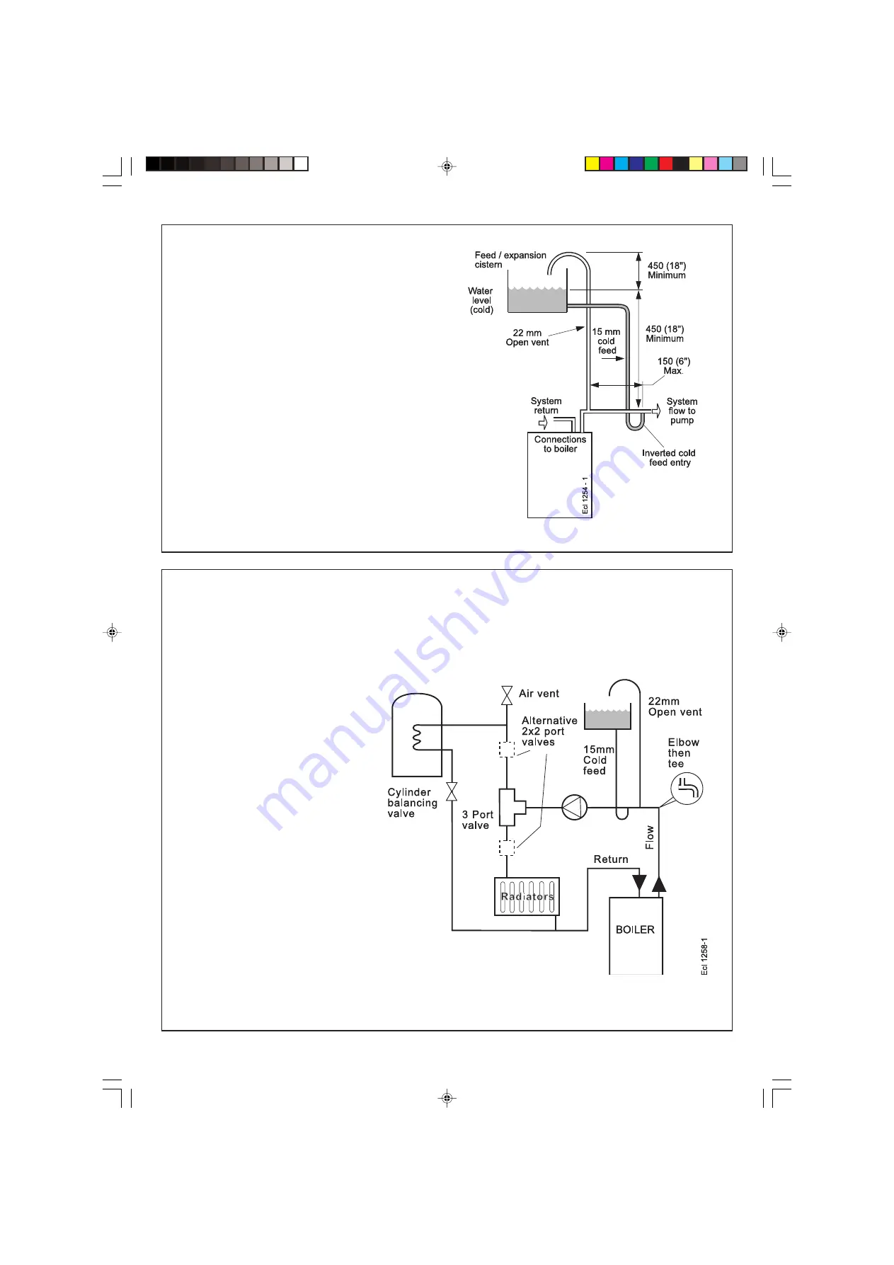
OPEN VENT SYSTEM REQUIREMENTS

4

SCHEMATIC PIPEWORK AND SYSTEM BALANCING

The boiler does not normally need a bypass but at least some
radiators on the heating circuit, of load at least 10% of the
minimum boiler output, must be provided with twin lockshield
valves so that this minimum heating load is always available
(see footnote re. thermostatic radiator valves).

Return & flow
connections

load 30 - 60 = 22 mm
load 70 - 80 = 28 mm

Balancing

1.

Set the programmer to ON for both CH
and HW.  Turn the cylinder thermostat
down.  Close the manual or thermostatic
valves on all radiators, leaving the twin
lockshield valves (on the radiators
referred to above) in the open position.
Turn up the room thermostat and adjust
these lockshield valves to give boiler flow
and return temperatures not more than
20 

o

C apart.  These valves should now be

left as set.

2.

Open all manual or thermostatic radiator
valves and adjust the lockshield valves
on remaining radiators to give around
11

o

C temperature drop at each radiator.

3.

Turn up the cylinder thermostat and
adjust the cylinder balancing valve so
that the cylinder achieves a maximum
flow consistent with adequate flow to the
radiators. Check that with only the
domestic hot water loop in circuit a
differential temperature of 20 

o

C across

the boiler is not exceeded.

4.

Adjust room and cylinder thermostats
and programmer to NORMAL settings.

The system should be vented directly off the boiler flow pipe, as
close to the boiler as possible. The cold feed entry should be
inverted and MUST be positioned between the pump and the vent,
and not more than 150mm (6") away from the vent connection.

Note.


Combined feed and vent pipes may also be fitted.

There should be a minimum height 450mm (18") of open vent
above the cistern water level. If this is not possible refer to
Frame 5

.

 The vertical distance between the highest point of the

system and the feed/expansion cistern water level MUST not be
less than 450 mm (18"). The pump must be fitted on the flow side of
the boiler.

A suitable pump is a domestic circulator capable of providing a
maximum 11

o

C (20

o

F) temperature differential across the boiler with the

whole of the heating circuit open (e.g. Grundfos UPS 15/50, 15/60 or
equivalent). With the minimum flow circuit allowed by the controls the
differential must not exceed 25 

o

C. (18

o

C for the HE15)

The vertical distance between the pump and feed/expansion cistern
MUST comply with the pump manufacturer's minimum requirements, to
avoid cavitation. Should these conditions not apply either lower the
pump position or raise the cistern above the minimum requirement
specified by 

Caradon Ideal Limited.

 The isolation valves should be

fitted as close to the pump as possible.

200212-10.pmd

9/5/2005, 8:58 AM

10

Summary of Contents for Optia HE 12

Page 1: ...he safety and performance specification that we require Do not use reconditioned or copy parts that have not been clearly authorised by Ideal Boilers HE12 HE15 HE18 HE24 For users guide see reverse of...

Page 2: ...2 icos Installation Servicing 200212 10 pmd 9 5 2005 8 58 AM 2...

Page 3: ...book from Mod Level A09 May 05 to A10 Sept 05 Page 15 Frame 11 Unpacking Mains Connector added to hardware pack contents Page 25 Frame 32 Pictorial Wiring Diagram Update to wiring diagram Caradon Ide...

Page 4: ...ight kg lb 38 84 Maximum installation weight kg lb 31 68 Boiler size Height mm in 582 23 Width mm in 390 15 Depth mm in 278 11 The value is used in the UK Government s Standard Assessment Procedure SA...

Page 5: ...ed For assistance see Technical Helpline on the back page Page Burner operating pressure n a Central heating flow temp measure and record Central heating return temp measure and record For combination...

Page 6: ...inside ONLY b If a core boring tool is to be used inside the building the space in which the boiler is to be installed must be at least wide enough to accommodate the tool Front clearance The minimum...

Page 7: ...ered Vertical Flue Kit to a maximum primary flue length of 8m a maximum secondary flue length of 6m Twin Flueing Kit to a maximum of 46m combined total of flue and air ducts Remote User Control Kit Bo...

Page 8: ...n existing meter should be checked preferably by the gas supplier to ensure that the meter is adequate to deal with the rate of gas supply required N B The principle of the 1 1 gas valve ensures that...

Page 9: ...CONDENSATE DRAIN Refer to Frames 23 44 A condensate drain is provided on the boiler This drain must be connected to a drainage point All pipework and fittings in the condensate drainage system MUST b...

Page 10: ...perature of 20 o C across the boiler is not exceeded 4 Adjust room and cylinder thermostats and programmer to NORMAL settings The system should be vented directly off the boiler flow pipe as close to...

Page 11: ...e pipe should be positioned so that the discharge of water or steam cannot create a hazard to the occupants of the premises or cause damage to electrical components and wiring 3 Pressure Gauge A press...

Page 12: ...e connected to a point close to the inlet side of the pump the connecting pipe being not less than 15 mm 1 2 nominal size and not incorporating valves of any sort b The vessel capacity must be adequat...

Page 13: ...d recommend water treatment in accordance with the Benchmark Guidance Notes on Water Treatment in Central Heating systems Caradon Ideal Limited recommend the use of FERNOX COPAL or MB1 GE Betz Sentine...

Page 14: ...bracket assy 21 Orifice plate LEGEND 1 Front casing panel 2 Sealing panel 3 Sump cover plate 4 Bottom casing panel 5 Flue sensing nipple 6 Return pipe 7 Flow pipe 10 BOILER ASSEMBLY Exploded view 22...

Page 15: ...User s Instructions F Water Treatment Warning Label G Hardware pack Pack B Contents A Flue turret B Flue terminal C Flue support cutting aid 1 Ensure the boiler is stood correctly as marked on the ca...

Page 16: ...8M POWERED VERTICAL FLUE KIT 14M TOTAL 60 60 TWIN FLUE KIT 20M TOTAL AIR PLUS FLUE DUCT 80 80 TWIN FLUE KIT 46M TOTAL AIR PLUS FLUE DUCT 90O ELBOW KIT 60 100 EQUIVALENT FLUE LENGTH RESISTANCE 1M 45O E...

Page 17: ...following a The 2 wall mounting plate screw positions choose one from each group and the jacking screw position If using the stand off kit mark on 4 screw positions choosing one from each group b The...

Page 18: ...then locate the stand off channel and screw home 19 CUTTING THE FLUE SIDE Wall thicknesses of 114 to 455mm 18 CUTTING THE FLUE REAR Wall thicknesses of 114 to 490mm Note If using the extension ducts g...

Page 19: ...Using the clamp provided clamp the flue lengths together 5 Repeat steps 1 4 if a second flue extension is required 6 Measure and mark the flue length required onto the flue measuring from the ring nea...

Page 20: ...sed The drain outlet on the boiler is standard 21 5mm overflow pipe This size must not be reduced in any part of its length A plastic cap is fitted to the end of the condensate drain adapter this must...

Page 21: ...Make connection to SVP using a solvent welded saddle BOILER External wall Ground Level Termination to Soak away cla7774 minimum 500mm BOILER External wall Ground Level Open end of pipe direct into gu...

Page 22: ...flue turret on top of the boiler by inserting the open ends of the turret clamp under the 2 studs and fixing it in the middle with the single M5 x 10mm pozi hex screw provided 5 Flues over 1 metre lo...

Page 23: ...s supply pipe length of 20m and not less than 15mm O D can be connected to the boiler via the gas service cock union Ensure that the gas supply pipe does not foul the boiler casing Refer to Frame 36 f...

Page 24: ...to function correctly 3 Wire the switched live supply into L2 or connect L1 and L2 via external control switching as shown in Frame 32 In either case remove the wire link fitted L1 to L2 4 Secure the...

Page 25: ...AL FLOW WIRING DIAGRAM Overheat thermostat 1 2 br r r bk y pk b Mains Switch Flame detection electrode DC Fan Ignition electrode CH return thermistor not fitted Control thermistor DC Gas valve b v bk...

Page 26: ...e 3A Room Thermostat If the thermostat has a neutral connection use it It provides for more energy efficient operation by reducing switching temperature differentials Frost Protection If parts of the...

Page 27: ...ler control should now go through its ignition sequence until the burner is established 10 If the boiler does not light after 3 attempts the fault codes L F will be displayed Press the reset button E...

Page 28: ...er of the precautions necessary to prevent damage to the system and to the building in the event of the system remaining inoperative during frosty conditions 4 Explain the function and the use of the...

Page 29: ...ar intervals and serviced as necessary The frequency of servicing will depend upon the installation condition and usage but should be carried out annually It is the law that any service work must be c...

Page 30: ...the rear are extended to ease access 2 Lift off the burner from the combustion chamber IMPORTANT The burner head is a ceramic plaque construction Care must be taken to ensure that the burner is not pl...

Page 31: ...10 Reconnect the electrical supply 1 Remove ignition and flame detection electrodes Refer to Frames 51 52 2 Remove the 3 screws retaining the sump cover and remove 3 Using a suitable tool as supplied...

Page 32: ...Frames 40 41 3 Pull the electrical leads off the control thermistor 4 Pull the control thermistor and spring clip off the IMPORTANT When work is complete the sealing panel must be correctly fitted ens...

Page 33: ...deterioration is visible 9 Fit the new fan venturi assembly 10 Reassemble the boiler in reverse order taking care not to overtighten the screw on the fan mounting bracket 11 Check the operation of the...

Page 34: ...maining screw holding the ignition electrode to the combustion chamber 6 Remove the electrode 5 Remove the flame detection electrode 6 Fit the new flame detection electrode using the new gasket suppli...

Page 35: ...s control valve 5 Undo the union nut between the gas valve and the gas inlet cock 6 Undo the union nut on the outlet side of the gas control valve 7 Undo the gas valve bracket screw slide the gas valv...

Page 36: ...4 Remove the 2 control box screws 5 Carefully unplug all the electrical wiring from the control box 6 With the control box lowered pull the assembly forward to remove from the housing 7 Remove the use...

Page 37: ...supplied 8 Reassemble in reverse order 9 Check operation of the boiler Refer to Frame 47 1 Refer to Frame 47 2 Remove the boiler front and sealing panels Refer to Frames 40 41 3 Pull off the electrica...

Page 38: ...supplied with the spare part 8 Damp down the combustion chamber area containing the insulation boards 9 Remove the split pin and washer from the RHS of the combustion chamber 10 Remove the insulation...

Page 39: ...lue casting spring clip 14 Undo the 2 M5 x 10 flue spring retaining bracket screws and remove the yoke plate 15 Pull the CH return pipe up and out of the heat exchanger 16 Unscrew the M5 x 10 screw re...

Page 40: ...t the boiler sealing panel is correctly seated compressing the seal to make an airtight joint 7 Check operation of boiler Refer to Frame 47 nm 2787 Seals 3 63 CONDENSATE S TRAP REPLACEMENT 1 Refer to...

Page 41: ...NG L A GO TO FRAME 67 ALTERNATING L 8 GO TO FRAME 68 ALTERNATING H 1 GO TO FRAME 69 ALTERNATING H F GO TO FRAME 70 ALTERNATING H 4 GO TO FRAME 71 ALTERNATING H n GO TO FRAME 72 ALTERNATING H E GO TO F...

Page 42: ...s necessary NO Replace gas valve YES NO NO 66 L E or H E BOARD ERROR Internal fault within the PCB Replace PCB Note Due to the wave form of the rectified voltage the reading will vary depending on the...

Page 43: ...y between the PCB and the thermistor Check resistance using a suitable multimeter connected across the thermistors terminal pins At 25 o C expect 9 700 10 300 Ohms At 60 o C expect 2 400 2 600 Ohms At...

Page 44: ...across the thermistor terminal pins At 25 o C expect 9 700 10 300 Ohms At 60 o C expect 2 400 2 600 Ohms At 85 o C expect 1 000 1 100 Ohms Are thermistor values correct Replace PCB Replace thermistor...

Page 45: ...ontrol valve 1 170 913 22 E67 500 Flue thermistor 1 170 916 23 E67 501 Control thermistor 2 170 917 24 E67 502 Overheat thermostat 1 170 918 25 Ignition electrode kit 1 173 528 26 Flame detection elec...

Page 46: ...llation Servicing SHORT LIST OF PARTS nm8077 73 SHORT LIST 74 BOILER CASING ASSEMBLY 1 Front casing panel with screws 2 Sealing panel with screws 4 Bottom casing panel with screws 200212 10 pmd 9 5 20...

Page 47: ...assembly with screws and gasket LIST OF PARTS 75 CONTROLS ASSEMBLY 33 Controls assy with screws 34 Controls hinge bracket 35 User controls without item 38 36 PCB primary controls 38 User control hous...

Page 48: ...48 icos Installation Servicing NOTES 200212 10 pmd 9 5 2005 8 59 AM 48...

Page 49: ...ding Control LABC who will arrange an inspection or contact a government approved inspector LABC will record the data and will issue a certificate of compliance If you notify via CORGI Scheme CORGI wi...

Page 50: ...REDUCER HAS BEEN FITTED FOR THE DOMESTIC HOT WATER MODE MEASURE RECORD GAS RATE ft3 hr MAXIMUM BURNER OPERATING PRESSURE IF APPLICABLE mbar COLD WATER INLET TEMPERATURE o C HOT WATER OUTLET TEMPERATU...

Page 51: ...MENTS SIGNATURE SERVICE 3 DATE ENGINEER NAME COMPANY NAME TEL No CORGI ID CARD SERIAL No COMMENTS SIGNATURE SERVICE 4 DATE ENGINEER NAME COMPANY NAME TEL No CORGI ID CARD SERIAL No COMMENTS SIGNATURE...

Page 52: ...ries of first class training courses for domestic commercial and industrial heating installers engineers and system specifiers For details of courses please ring 01482 498 432 CERTIFIED PRODUCT Manufa...

Page 53: ...are parts that you can be assured conform to the safety and performance specification that we require Do not use reconditioned or copy parts that have not been clearly authorised by Ideal Boilers HE12...

Page 54: ...egistered installer or in IE a competent person In cases of repeated or continuous shutdown a CORGI registered installer or in IE a competent person should be called to investigate and rectify the con...

Page 55: ...consult a CORGI registered installer or in IE a competent person Flame failure Should this occur a fault code L F will be displayed Press the reset button and the boiler will relight If the fault rec...

Page 56: ...r domestic hot water Test by overriding the programmer by setting to continuous Check room thermostat for central heating or the cylinder thermostat for domestic hot water are set at the required temp...

Reviews: