25
icos system condensing -
Installation and Servicing
INSTALLATION
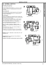
34 FUNCTIONAL FLOW WIRING DIAGRAM
WARNING.
Whilst effecting the required gas soundness test and purging air from the gas installation,
open all windows and doors, extinguish naked lights and
DO NOT SMOKE.
A. Electrical Installation
1.
Checks to ensure electrical safety should be carried out by
a competent person.
2.
ALWAYS carry out the preliminary electrical system checks,
i.e. earth continuity, polarity, resistance to earth and short
circuit, using a suitable test meter.
B. Gas Installation
1.
The whole of the gas installation, including the meter,
should be inspected and tested for soundness and
purged in accordance with the recommendations of BS.
6891.
2.
Purge air from the gas installation by approved methods
only.
3.
Retighten the union and test for gas soundness.
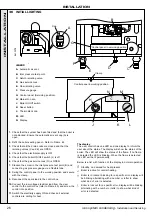
35 COMMISSIONING AND TESTING
bk
or
or
v
v
Pump
p
br
y/g
b
y/g
DC Gas valve
Overheat
thermostat
b
r
br
Mains Switch
DC
Fan
r
bk
y
pk
b
Flame detection electrode
y/g
r
r
Flue thermistor
y
y
gy
gy
r
r
Control thermistor
electrode
Ecl 1991
3
2
1
CH return thermistor
(not fitted)
br
y/g
y/g
br
bk
N
L
E
b
b
Filter
External switch e.g.
room'stat, programmer
PCB No.
P
HC
033
LEGEND
b
- blue
bk
- black
br
- brown
r
- red
pk
- pink
y
- yellow
w
- white
y/g
- yellow/green
gy
- grey
or
- orange
INST
ALLA
TION
Summary of Contents for icos system m3080
Page 1: ......
Page 51: ...51 icos system condensing Installation and Servicing NOTES ...
Page 53: ......

