13
icos system condensing -
Installation and Servicing
INSTALLATION
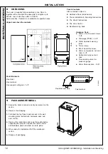
FLUE KITS
Pack B
- supplied as standard
Pack D
- optional extension kit for side flue
or rear flue outlet.
Refer to 'Flue Extension Ducts'
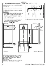
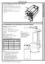
10 BOTTOM PANEL AND FRONT PANEL REMOVAL
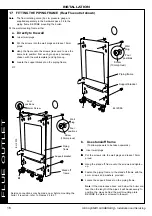
IMPORTANT.
The boiler MUST be installed
in a vertical position
Dimension X - Wall thickness.
Dimension L - Wall thickness plus boiler spacing .
Dimension S - Stand-off kit depth = 33mm.
1.
Undo the 4 retaining screws.
2.
Allow the RHS of the bottom panel to lower slightly.
3.
Withdraw the LHS of the bottom panel from the retaining
clips.
4.
Lift front panel and remove.
5.
Place bottom and front panel to one side to avoid
damage.
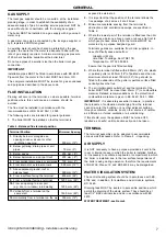
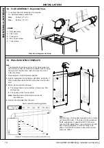
11 DETERMINING THE FLUE LENGTH AND FLUE PACKS REQUIRED
Notes.
1.
The flue duct MUST be inclined at 1.5 degrees
to the horizontal to allow condensate to drain
back into the boiler and out through the
condensate drain.
2.
If the boiler is to be installed with upward
piping routed behind the boiler then the
optional stand-off kit should be used. Care
must be taken when cutting the ducts and
marking wall to suit this condition.
Total Flue length dimension
Flue
Rear flue
Side
Extra packs
dim. X+160
flue dim. L+195
required
Up to 480 mm
Up to 480 mm
none
Up to 1430 mm
Up to 1430 mm
Pack D - 1 off
Up to 2380 mm
Up to 2380 mm
Pack D - 2 off
Up to 3000 mm
Up to 3000 mm
Pack D - 3 off
2008
160mm
160 + S = 193mm
2067
Bottom panel
Front panel
Retaining clip
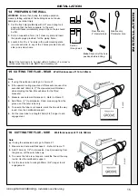
Note.
Powered Vertical Flue and
Roof Flue Kits are
available as optional extras
for vertical flue installations,
supplied with separate
fitting instructions.
INST
ALLA
TION
Summary of Contents for icos system m3080
Page 1: ......
Page 51: ...51 icos system condensing Installation and Servicing NOTES ...
Page 53: ......


