

8
Innovative Circuit Technology Ltd.
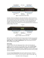
Alarm 3-pin connector plugs, and installing in the back panel. Each Bus Alarm
output will trigger for any fuse or breaker open, or other alarm related to any
channel on that bus (Factory Default). Most alarm conditions can be masked off
so that they will not trigger the Alarm output if required, using the web based
graphical interface.
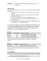
Bus Alarm Connector:
Connect up to 5 dry contact type site sensors (such as door/window sensors,
smoke alarm, water detectors etc.) by stripping and terminating 16-28AWG
alarm wiring and connecting to the five Site Alarm Inputs on the 10 pin
removable Alarm Input Plug, if desired. These inputs may be configured to
activate the panel Alarm outputs, or send an alarm e-mail on network connected
units. The external sensor contacts must be voltage free; as a small sense current
is supplied from the panel Alarm Input pins to detect the external contact open
or closed state. Refer to the Web Based Utility section for information on how to
configure and use the five Site Alarm inputs.
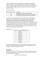
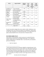
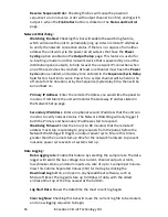
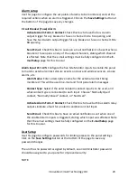
Site Alarm Inputs:
Pin (L-R)
Site Alarm Input Function
1
Input 1
c
Common
2
Input 2
c
Common
3
Input 3
c
Common
4
Input 4
c
Common
5
Input 5
c
Common
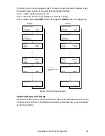
Connect a standard 10/100 Base-T Ethernet cable to the RJ-45 LAN port on the
back panel, if remote network control is planned or if reconfiguring the panel
settings from the factory defaults is required.
OPERATION
Ensure the correct fuses or circuit breakers are installed in each channel location
that will be used to power a load, and switch the front panel channel breakers
into the ON position (if equipped).
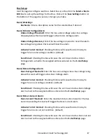
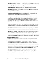
Alarm Pin (Bus A or B) Function
C
Alarm Output common (0.5A 65Vdc max)
NC
Alarm Output normally closed for alarm condition
NO
Alarm Output normally open for alarm condition


