6
Innovative Circuit Technology Ltd.
Ensure the total power consumption of the loads does not exceed the 80A
(continuous) rated capacity of each power bus
Channel output breakers or fuses must not exceed 25A max rating for
12/24VDC systems, 15A max for nominal 48VDC systems
Install only 80VDC rated fuses, 15 A max each for nominal 48Vdc systems
Install only 65VDC rated breakers, 15 A max each for nominal 48Vdc systems
Do not block air inlet or outlet openings in the panel sides
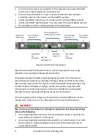
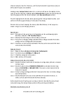
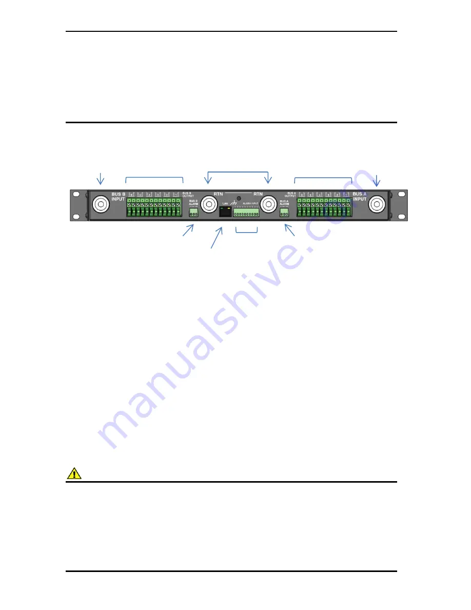
Figure 1: Back Panel Connections
Mount the Dual Bus Distribution Panel in a 19 inch equipment rack, using
standard rack mounting hardware. (Not provided)
On breaker equipped models install appropriately rated circuit breakers in
desired channel locations by carefully inserting a breaker so that its mounting
tabs securely snap into the front panel. Install the breaker blanking plugs in any
unused locations. Breakers and plugs may be removed by using two small
screwdrivers or similar tools to press in the top and bottom mounting tabs
through the cover openings and gently prying out of the panel.
On fuse equipped units change any channel fuses requiring different current
ratings. (Up to 25A max on 12 or 24V systems, 15A max on 48V systems)
WARNING
Risk of serious personal injury or damage to equipment and property! Always
observe the following:
Use an appropriately rated over-current protection device in line with the
main battery connections to the panel
Use an appropriately rated disconnect switch or circuit breaker in line with
the dc inputs to enable installation and service of the panel with the dc
source disconnected
Bus A Outputs
Channel 1-6
Bus B Outputs
Channel 1-6
Bus A/B Input RTN
Connectors (common)
Bus B Input
(100A max)
Bus A Input
(100A max)
Site Alarm
inputs 1-5
Bus A Alarm
out
C/NC/NO
Bus B Alarm
out
C/NC/NO
LAN Port
10/100
Base-T


