
18
Innovative Circuit Technology Ltd.
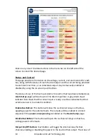
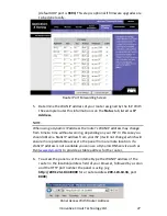
Output Setup
Use this page to configure the settings for each output channel on Bus A and Bus
B. Select the output to be edited in the
Select an Output to Edit
box. Make any
required changes, and then click on the
Save Settings
button at the bottom of
the page to save any edits. Click on the
Copy Settings to All
button, to copy the
settings of the selected output to all other outputs on both buses.
Output Settings:
Output Label
: Enter a descriptive label for the selected output channel if
desired.
Output State After Panel Reset
: Sets the state for the output after an input
power failure, or soft reset of the panel. Select one of the following:
Restore last State
: Will return the output contactor to the state
prior to the reset event (default)
Enable Output
: Will enable the output contactor, regardless of
its previous state
Disable Output
: Will disable the output contactor, regardless of
its previous state
Ignore Fuse/Circuit Breaker Status:
Will mask the fuse or circuit breaker
open circuit detection, to prevent false alarms on unused channels.
Enable Power Cycling:
Check this box to enable output power cycling for the
selected output, so that the output will automatically be re-enabled after
the
Sequence/Cycle Delay
time whenever the output is disabled using the
Output Off
button on the
Status and Control
page, or when the
Network
Watchdog
is triggered. This feature is useful for remotely resetting power to
hardware required for the network connectivity of the panel.
The
Sequence/Cycle Delay
time must be set on the
Device Setup
page with
duration long enough for the connected network hardware to fully reset for
this function to be effective. Multiple outputs that are disabled using Power
Cycling will be re-enabled in sequence.
Output Load Shedding:
Enable Load Shedding
: Check this box to disable this output when the bus
voltage drops below the load-shedding threshold for at least 30s. This
feature can be used to disconnect less critical loads to preserve back-up
battery power as the battery voltage drops.
Load-Shedding Threshold
: Enter the voltage level at which the selected
output will be disconnected.


